



Track-and-hold-sample-and-hold
Channel 1 is wired as a voltage follower and is turned on during the track/sample time. Ifthe product of R x Cis sufficiently short compared to the period of m...

Sample-and-hold
The LM101A provides gain and buffers the input from storage capacitor C2. R2 adds a zero in the open loop response to compensate for the pole caused by the swi...

Sample-and-hold
The sample-and-hold function has often been accomplished with separate analog switches and op amps. These designs always involve performance tradeoffs betwee...

Filtered-sample-and-hold
Itis often required that a signal be filtered prior to sampling. This can be accomplished with only one device. Use any of the inverting and noninverting fil...

High-speed-sample-and-hold
This circuit uses the speed and drive capability of the HA-5190 coupled with two high-speed DMOS FET switches. The input amplifier is allowed to operate at a g...

Basic-track-and-hold-sample-and-hold
Feedback is the same as a conventional op-amp voltage follower which yields 11 unity-gain, noninverting output. This hookup also has a very high input impeda...

Sample-and-hold
Two important properties of the 8043 are used to advantage in this circuit. The low input bias currents give rise to slow output decay rates (droop) in the hol...

1Mhz-meter-driver-amplifier
This circuit uses the CA3100 BiMOS op amp to drive~a 1-mA meter movement to full scale ...
Diodeless-precision-rectifier
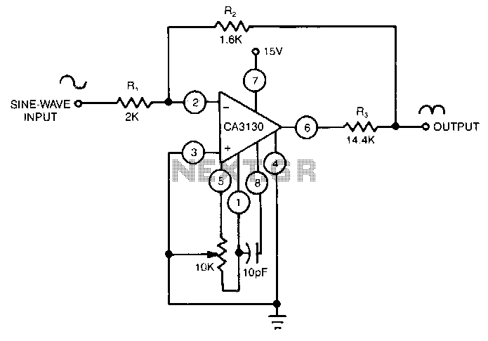
A CA3130 BiMOS op amp, acts as an attenuator for positive inputs and as a conventional op amp for negative signals. ...

Precision-full-wave-rectifier
This circuit provides accurate full-wave rectification. The output impedance is low for both input polarities, and the errors are small at all signal levels. N...

Integrator-ramp-generator-with-initial-condition-reset
Channell is wired as a conventional integrator, and channel2 as a voltage follower. When channel2 is switched on, the output will follow VJN and C will dischar...

Line-voltage-monitor
This circuit uses a type 741 op amp as a voltage comparator. One input of the 7.41 is connected to a reference voltage (a 12-V battery) through a resistor volt...

Programmable-amplifier
Often a circuit will be called upon to perform several functions. In these situations, the variable gain configuration of this circuit could be quite useful. ...

Digitally-programmable-precision-amplifier
The DG419looks into the high input impedance of the op amp, so the effects of Rvs(o"l are negligible. The DG441 is also connected in series with RIN and is not...

Noninverting-programmable-gain-amplifier
This is a noninverting amplifier configuration with feedback resistors chosen to produce a gain of 0, 1, 2, 4, or 8, depending on the digital control inputs. ...

Inverting-programmable-gain-amplifier
This circuit can be programmed for a gain of 0, -1, -2, -4, or -8. This could also be accomplished with one input resistor and one feedback resistor per chan...

Stabilized-capacitance-buffer
Ql and Q2 constitute a simple, high-speed FET input buffer. Ql functions as a source follower, with the Q2 current source load setting the drain-source channel...

Low-input-capacitance-buffer
Ql and Q2 constitute a simple, high-speed FET input buffer.·Ql functions as a source follower, with the Q2 current-source load setting the drain-source chan...

Safe-constant-current-source
In the circuit shown, a CMOS op amp controls the current through a p-channel HEXFET power transistor to maintain a constant voltage across RL The current is gi...

Bilateral-current-source
This circuit uses a CA3193 precision op amp to deliver a current independent of variations in RL. With RI set equal to R3, and R2 approximately equal to R4 +...