


Digital Compass Module HMC6352
#HMC6352
#digital compass
#I2C
#microprocessor
#sensor module
#magnetometer
#navigation
#3V logic
#pull-up resistors
#serial communication

Description: In Figure 1, the host microprocessor (uP) manages the HMC6352 through I2C serial data interface lines designated for data (SDA) and clock (SCL). Two external 10k-ohm pull-up resistors connected to a nominal 3-volt DC supply establish normally high logic levels when the interface lines are inactive. The host begins communication by generating a 100kHz clock signal and pulling the data line low to indicate the start condition. Transitions in the data line logic state are permitted only during the low states of the clock, necessitating that the data line remains stable during high states, except during start and stop conditions. The 0.01µF supply decoupling capacitor mentioned can be omitted if another supply filter capacitor is already present in the overall circuit design. If the supply traces extend more than a couple of inches to the HMC6352, it is recommended to include a local supply decoupling capacitor near the HMC6352 to ensure optimal circuit stability. Additional master and slave devices can be integrated into the I2C bus traces without causing issues with the HMC6352. No periodic maintenance commands are required, and the HMC6352 can enter sleep mode or power down without affecting the data or clock lines.
The described circuit involves a microprocessor interfacing with the HMC6352 via the I2C protocol, which is a widely used communication standard for connecting microcontrollers and peripheral devices. The use of the 10k-ohm pull-up resistors is crucial for maintaining the logic levels on the SDA and SCL lines when they are not actively driven. This ensures that the lines are pulled to a high state, which is essential for the proper functioning of the I2C protocol.
The initiation of communication starts with the microprocessor generating a clock signal at a frequency of 100kHz. This clock signal is vital for synchronizing the data transfer between the microprocessor and the HMC6352. The start condition, indicated by pulling the SDA line low while the SCL line is high, signals the beginning of data transmission. It is important to adhere to the timing requirements of the I2C protocol, particularly that the data line must remain stable during the high state of the clock to prevent erroneous data interpretation.
Decoupling capacitors play a critical role in stabilizing the power supply to the HMC6352. While the 0.01µF capacitor can be omitted if a suitable filter capacitor is already in place, it is advisable to add a local decoupling capacitor near the HMC6352 if the supply traces are lengthy. This practice minimizes voltage fluctuations and noise, enhancing the performance and reliability of the circuit.
The I2C bus allows for multiple devices to be connected, facilitating a flexible and expandable system architecture. The ability to add additional master and slave devices without interference is a significant advantage of the I2C protocol. Furthermore, the HMC6352's capability to enter sleep mode or shut down without affecting the integrity of the data or clock lines underscores its robustness in low-power applications. Overall, this circuit design promotes efficient communication and stability, catering to the needs of modern electronic systems.From Figure 1, the host microprocessor (uP) controls the HMC6352 via I2C serial data interface lines for data (SDA) and clock (SCL). Two external 10k-ohm pull-up resistors to the nominal 3 volt DC supply create normally high logic states when the interface lines are not in use.
The host initiates use of the interface by creating the 100kHz clock a nd pulling low the data line to indicate the start condition. The data line logic state transitions are only allowed during the clock low states and require the data line to be stable in the high states, with the exception of the start and stop conditions. The 0. 01uF supply decoupling capacitor in this reference can be omitted if another supply filter capacitor is already included in the overall circuit design.
If the supply traces extend beyond a couple inches to the HMC6352, it is advisable to add a local supply decoupling capacitor near the HMC6352 to retain optimum circuit stability. Additional masters and slaves can be added to the I2C bus traces without interface trouble to the HMC6352.
There are no periodic maintenance commands required, and even HMC6352 sleep mode or power shutdown can be accomplished without harm to the data or clock lines.
The described circuit involves a microprocessor interfacing with the HMC6352 via the I2C protocol, which is a widely used communication standard for connecting microcontrollers and peripheral devices. The use of the 10k-ohm pull-up resistors is crucial for maintaining the logic levels on the SDA and SCL lines when they are not actively driven. This ensures that the lines are pulled to a high state, which is essential for the proper functioning of the I2C protocol.
The initiation of communication starts with the microprocessor generating a clock signal at a frequency of 100kHz. This clock signal is vital for synchronizing the data transfer between the microprocessor and the HMC6352. The start condition, indicated by pulling the SDA line low while the SCL line is high, signals the beginning of data transmission. It is important to adhere to the timing requirements of the I2C protocol, particularly that the data line must remain stable during the high state of the clock to prevent erroneous data interpretation.
Decoupling capacitors play a critical role in stabilizing the power supply to the HMC6352. While the 0.01µF capacitor can be omitted if a suitable filter capacitor is already in place, it is advisable to add a local decoupling capacitor near the HMC6352 if the supply traces are lengthy. This practice minimizes voltage fluctuations and noise, enhancing the performance and reliability of the circuit.
The I2C bus allows for multiple devices to be connected, facilitating a flexible and expandable system architecture. The ability to add additional master and slave devices without interference is a significant advantage of the I2C protocol. Furthermore, the HMC6352's capability to enter sleep mode or shut down without affecting the integrity of the data or clock lines underscores its robustness in low-power applications. Overall, this circuit design promotes efficient communication and stability, catering to the needs of modern electronic systems.From Figure 1, the host microprocessor (uP) controls the HMC6352 via I2C serial data interface lines for data (SDA) and clock (SCL). Two external 10k-ohm pull-up resistors to the nominal 3 volt DC supply create normally high logic states when the interface lines are not in use.
The host initiates use of the interface by creating the 100kHz clock a nd pulling low the data line to indicate the start condition. The data line logic state transitions are only allowed during the clock low states and require the data line to be stable in the high states, with the exception of the start and stop conditions. The 0. 01uF supply decoupling capacitor in this reference can be omitted if another supply filter capacitor is already included in the overall circuit design.
If the supply traces extend beyond a couple inches to the HMC6352, it is advisable to add a local supply decoupling capacitor near the HMC6352 to retain optimum circuit stability. Additional masters and slaves can be added to the I2C bus traces without interface trouble to the HMC6352.
There are no periodic maintenance commands required, and even HMC6352 sleep mode or power shutdown can be accomplished without harm to the data or clock lines.

8-direction Digital Compass Using Z8 Encore
The M-8880 is a complete DTMF Transmitter/Receiver that features adjustable guard time, automatic tone burst mode, call progress mode, and a fully compatible 6500/6800 microprocessor interface. The receiver portion is based on the industry-standard M-8870 DTMF Receiver, while the transmitter...

I2C Interfacing Acceleration Sensing PCF8591
This section of the I2C interfacing project focuses on constructing an acceleration sensor while also addressing two additional aspects: the advanced application of the PCF8591 chip (previously discussed in the context of the pressure sensor) and operating the bus at...

Digital Compass for PC
The digital navigation PC board may be configured for a number of navigation functions. It may be made into a simple visual digital compass, or a microcontroller based compass. The microcontroller based compass can be used for mobile robotics or...

Microprocessor RS-232 Reset
This circuit allows a remote microprocessor to be reset by a controlling host over a remote RS-232 or similar protocol serial line. With the use of a program loader on the remote host, a program may be downloaded and run....

I2C Bus I2C Interface description
The I2C bus employs a bi-directional Serial Clock Line (SCL) and Serial Data Line (SDA). Both the SCL and SDA lines are pulled high using a pull-up resistor (Rp). An optional resistor (Rs) is utilized for ESD protection in hot-swap...
Electrical Isolation For I2C Bus
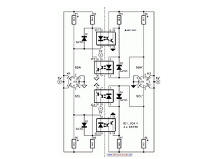
When the SDA (Serial Data) lines on both the left and right lines are high (logic level 1), the circuit remains in a quiescent state, and the optoisolators IC1 and IC2 are not activated.
In this circuit, the Serial Data...

I2C using (MSSP)
I2C are widely use for to communicate with external peripheral such as port expender, EEPROM, Real Time Clock etc. The Master Synchronous Serial Port (MSSP) module in PIC18 can be used to communicated with I2C peripheral. MSSP module can be...

Digital Compass
A four-output Hall sensor combined with several logic gates produces this digital compass. The NOR gates resolve the four Hall outputs into eight distinct compass directions. LEDs to indicate direction are driven by eight inverters. A power supply for 5.25...
microprocessor Map processor to circuit diagram
How the processor produces 3 as the output. This question may be challenging to answer in simple terms. If so, a link to a book would be helpful.
The process by which a processor generates the output of the number 3...