Encoders and Decoders
1. Definition and Purpose of Encoders
1.2 Types of Encoders: Absolute vs. Incremental
In the realm of encoders, two primary distinctions arise – absolute encoders and incremental encoders. Let's delve into the characteristics of each type and explore their functionalities in various applications.
Absolute Encoders
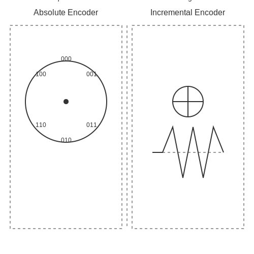
Absolute encoders provide information about the absolute position of the encoder shaft at any given point in time. They directly indicate the exact position without needing any reference point or initialization. Each position on the encoder disk corresponds to a unique digital code, ensuring precise positioning information.
A crucial aspect of absolute encoders is their ability to maintain position data even during power outages or system resets. This feature makes absolute encoders essential in applications requiring high accuracy and reliability, such as robotic systems, CNC machines, and astronomical instruments.
Incremental Encoders
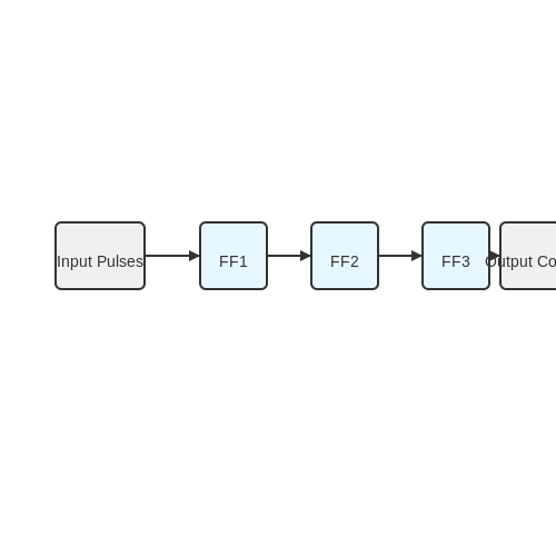
In contrast, incremental encoders generate a series of pulses as the encoder shaft rotates, providing relative motion information rather than absolute position data. These pulses, typically in the form of square waves, are used to track the relative movement of the encoder shaft.
One key characteristic of incremental encoders is their simplicity and cost-effectiveness compared to absolute encoders. However, since they do not provide absolute position information, incremental encoders often require a reference point or initial calibration to determine the starting position.
Despite this limitation, incremental encoders are widely used in speed and motion control applications where precise position feedback is not as critical. Examples include conveyor belts, motor control systems, and velocity sensing applications.
Practical Applications and Considerations
Choosing between absolute and incremental encoders depends on the specific requirements of the application. Absolute encoders are favored in scenarios demanding high accuracy and reliability, while incremental encoders offer cost-effective solutions for applications prioritizing relative motion tracking.
Real-world systems often integrate both types of encoders to leverage the strengths of each approach. This hybrid setup combines the precision of absolute encoders with the simplicity and cost efficiency of incremental encoders, providing a comprehensive solution for diverse applications.
Working Principle of Encoders
Encoders are essential devices in electronics used to convert information from one format to another, such as from physical movement to digital signals. Understanding the working principle of encoders is crucial for various applications in robotics, automation, and control systems.Basic Working Principle
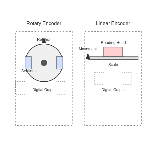
At its core, an encoder generates digital signals based on the position or movement of an object. There are primarily two types of encoders: rotary encoders for rotational movement and linear encoders for linear motion.
Rotary encoders typically consist of a rotating disc with slots or marks and sensors that detect these changes. As the encoder disk rotates, the sensors generate digital pulses based on the movement, which can be used to determine the position, speed, or direction of rotation.
On the other hand, linear encoders work similarly but in a linear fashion. They use a scale and reading head to generate digital signals corresponding to linear displacement.
Types of Encoders
Encoders can be further classified into incremental encoders and absolute encoders. Incremental encoders produce pulses in response to movement and rely on a reference point for accurate position determination. In contrast, absolute encoders provide a unique digital code for each position, allowing precise position tracking without needing a reference point.
Applications in Industry
Encoders find widespread use in various industries, such as robotics, CNC machines, conveyor systems, and more. In robotics, encoders play a critical role in determining the precise position and movement of robotic arms or actuators. In CNC machines, encoders help track the tool position accurately, ensuring precise machining operations.
2. Electrical Output Signals: Digital vs. Analog
2.1 Electrical Output Signals: Digital vs. Analog
In the realm of encoders and decoders, the distinction between digital and analog signals is fundamental. Understanding the characteristics and applications of these signal types is crucial for advanced professionals in fields like engineering, physics, and research.
Digital Signals
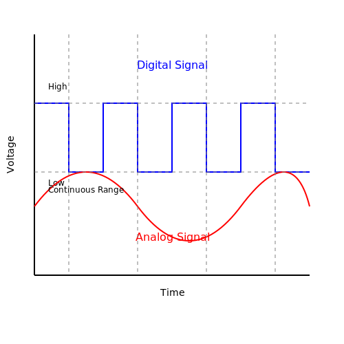
Digital signals are discrete, representing information in binary form (0s and 1s). These signals are robust against noise, making them highly reliable for long-distance transmission. The signal's value is determined by its voltage level, which could be either high (logical 1) or low (logical 0).
Digital signals simplify signal processing and offer precise signal regeneration capabilities, crucial in digital communication systems like Ethernet, USB, and HDMI.
Analog Signals
Contrary to digital signals, analog signals vary continuously over time. These signals have infinite possible states within a defined range, making them ideal for applications that require precise representation of real-world data, such as audio and image processing. The signal's magnitude directly corresponds to the physical quantity being measured.
Analog signals are susceptible to noise interference and distortion over long transmission distances. However, they are essential in scenarios where exact representation of data is critical, like in scientific instruments and control systems.
Comparison and Applications
The choice between digital and analog signals depends on the specific requirements of the application. Digital signals excel in high-speed communication, data storage, and processing, while analog signals are vital for accurate sensory data acquisition and generation where continuous variation is essential.
Understanding the characteristics and applications of digital and analog signals is fundamental to designing efficient and reliable systems in modern electronics and communication technologies.
2.2 Interfacing Encoders with Microcontrollers
In the realm of electronics, interfacing encoders with microcontrollers is a crucial aspect of various advanced systems, ranging from robotics to automation. Encoders, devices that convert angular or linear position into electrical signals, play a fundamental role in providing feedback for precise motion control. ### Understanding Encoder Types: Encoders are broadly categorized into two main types: incremental encoders and absolute encoders. Incremental encoders generate a series of pulses when moved, allowing microcontrollers to track position changes. On the other hand, absolute encoders provide a unique digital code for each position, enabling precise position determination even after power loss. #### Control Interface: When interfacing encoders with microcontrollers, the choice of interface depends on factors like resolution, cost, and noise immunity. Common interfaces include TTL, RS-422, and SSI. TTL is simple and cost-effective, suitable for short-distance applications, while RS-422 offers superior noise immunity over long distances. SSI, with synchronous data transmission, provides high resolution for precise control systems. ### Wiring and Signal Processing: The wiring scheme for encoders typically involves connecting the encoder outputs to the microcontroller inputs. Signal processing is crucial, involving debouncing for reliable signal interpretation and filtering for noise reduction. Additionally, the microcontroller must be programmed to interpret encoder signals accurately and efficiently. #### Practical Application: Consider a robotic arm controlled by a microcontroller interfaced with encoders. The encoders on the arm's joints provide feedback to the microcontroller, enabling precise control of each joint's position. This system exemplifies the practical relevance of interfacing encoders with microcontrollers in advanced mechatronic applications. ### Mathematical Background: In the context of encoder interfacing, understanding the pulse count, resolution, and signal processing algorithms is paramount. Mathematical derivations guide the development of efficient encoder signal processing routines within microcontroller firmware.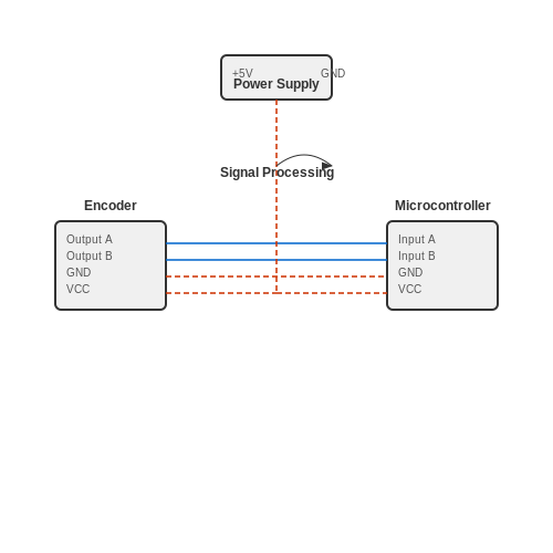
2.3 Signal Processing and Error Correction
In the realm of signal processing and error correction in encoders and decoders, advanced techniques are employed to ensure accurate transmission and reception of data. Signal processing encompasses a range of methods used to manipulate and analyze signals, while error correction aims to detect and rectify errors that may occur during data transmission.
Signal Processing Techniques
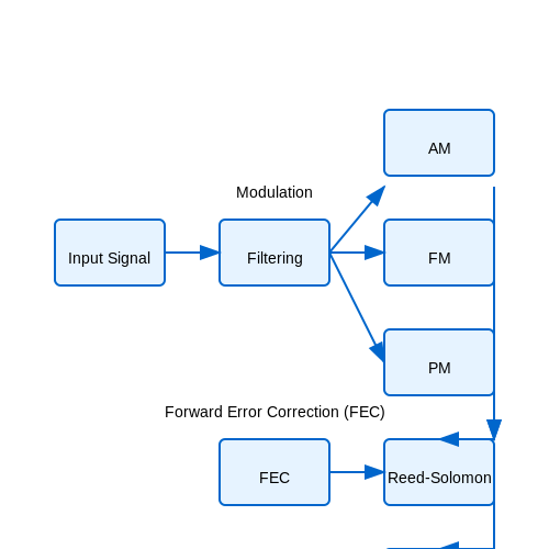
Signal processing in the context of encoders and decoders involves various strategies to enhance the quality and reliability of transmitted data. One fundamental approach is filtering, which helps in removing unwanted noise and interference from the signal. Filters can be implemented using digital or analog components, depending on the application requirements.
Another crucial aspect of signal processing is modulation, where the characteristics of the signal are modified to carry information efficiently. Modulation techniques like Amplitude Modulation (AM), Frequency Modulation (FM), and Phase Modulation (PM) are commonly used in communication systems to encode data onto carrier signals.
Here, SNR represents the Signal-to-Noise Ratio, Ps denotes the signal power, and Pn stands for the noise power.
Error Correction Mechanisms
Error correction techniques play a pivotal role in ensuring data integrity, especially in scenarios where noise or interference may corrupt the transmitted information. One widely used method is Forward Error Correction (FEC), which involves adding redundant information to the data stream so that errors can be detected and corrected at the receiving end.
Reed-Solomon codes are a form of FEC that provide robust error correction capabilities and are utilized in various communication systems, including digital television and satellite communications.
Practical Applications
The concepts of signal processing and error correction are extensively applied in modern communication systems such as wireless networks, optical fiber communications, and satellite links. By employing sophisticated algorithms and protocols, engineers can ensure reliable data transmission even in challenging environments with high noise levels.
Understanding signal processing and error correction mechanisms is crucial for designing efficient encoding and decoding systems that can operate effectively across different communication channels and under varying conditions.
3. Definition and Purpose of Decoders
3.1 Definition and Purpose of Decoders
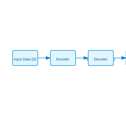
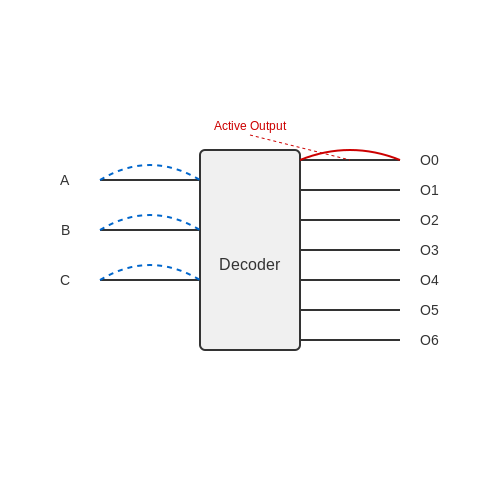
In digital electronics, decoders are critical components that play a key role in signal processing and data transmission. Decoders are designed to receive coded input signals and convert them into a specified set of output lines based on the input configuration. These devices are fundamental in various applications, including memory systems, address decoding, data demultiplexing, and control logic.
Decoders essentially perform the inverse function of encoders by interpreting the coded input and activating the corresponding output line. This decoding process enables efficient communication and control within digital systems. Understanding the operation and significance of decoders is essential for advanced electronics and communication engineering.
Decoders are commonly used in conjunction with encoders to enable bidirectional data flow and facilitate complex data processing tasks. This subsection delves into the detailed workings of decoders, their applications in real-world scenarios, and the principles that govern their functionality.
Types of Decoders: Binary, Decimal, and BCD
Decoders play a crucial role in digital electronics, serving to convert encoded information into a more understandable form. Here, we delve into the different types of decoders, each with its unique applications and characteristics.Binary Decoder
A binary decoder is one of the fundamental types of decoders. It takes binary input and produces a single output line among 2^n possible output lines based on the input combination. Mathematically, if the decoder has n input lines, it will have 2^n output lines. Binary decoders find extensive use in digital display systems, address decoding in memory units, and control circuits in microprocessors where binary signals need to be converted into specific control signals.Decimal Decoder
Moving beyond binary, decimal decoders accept BCD (Binary Coded Decimal) inputs and produce output lines corresponding to decimal values. These decoders are crucial for applications where input and output need to be in decimal form, such as in digital clocks, calculators, and other devices that handle decimal information. The conversion from BCD to decimal involves mapping the 4-bit binary input to its decimal equivalent. For example, with inputs A, B, C, and D, the decimal output can range from 0 to 9.BCD Decoder
BCD decoders specifically cater to BCD inputs where each decimal digit is represented by its 4-bit binary equivalent. These decoders are designed to take these BCD inputs and produce corresponding decimal outputs. BCD decoders are essential in applications where decimal representation is critical, such as in timekeeping systems and digital arithmetic circuits. BCD decoders typically involve analyzing each BCD input combination and activating the corresponding output line based on the binary-to-decimal mapping. In summary, decoders, whether binary, decimal, or BCD, are fundamental components in digital systems, enabling the conversion of encoded information into a format usable by various digital circuits and systems. Their versatility and critical role make them indispensable in modern electronics applications.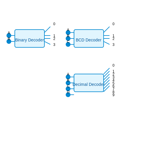
3.3 Working Principle of Decoders
In the realm of digital electronics, decoders play a vital role in converting coded data into a set of outputs. Understanding their working principle is crucial for advanced-level engineers and researchers.
Decoders typically have n number of inputs and 2n outputs. These outputs are activated based on specific input combinations, making decoders essential in various applications, such as memory systems, data transmission, and address decoding.
Functionality and Boolean Logic
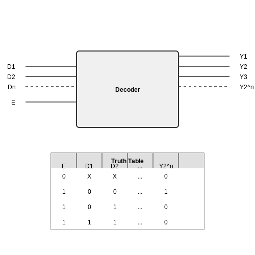
Decoders operate based on Boolean logic, where each output corresponds to a specific input combination. For an n-input decoder, each input corresponds to a unique output line. This behavior follows the truth table principle where each row represents a unique binary input pattern and its resulting output.
Enable Inputs
Sometimes decoders include enable inputs to control the activation of outputs. These enable inputs determine if the decoder should respond to the inputs or remain idle. This feature provides flexibility in the operation of decoders, allowing for selective activation and deactivation of output lines.
Practical Applications
The practical applications of decoders are vast and varied. They are utilized in addressing memory systems, controlling peripheral devices, and even in demultiplexing data streams. By understanding the working principle, engineers can effectively design and implement decoders in complex electronic systems.
Key Applications of Decoders
Decoders have numerous applications in various fields due to their ability to convert coded information into a specific output. Here are some key applications of decoders:
1. Digital Electronics
In digital electronics, decoders are essential components in circuits that perform tasks such as data demultiplexing, address decoding for memory systems, and input signal processing.
2. Communication Systems
Decoders play a crucial role in communication systems for error detection and correction, data encryption and decryption, channel coding and modulation, and signal processing.
3. Computer Science
In computer science, decoders are used in instruction decoding in CPUs, addressing memory locations, controlling peripherals, and interpreting various data formats.
4. Automation and Control Systems
Decoders are employed in automation and control systems to interpret input signals, process sensor readings, control actuators, and implement logical decision-making tasks.
5. Image and Video Processing
Decoders are utilized in image and video processing applications to decode compressed media files, stream multimedia content, display graphics, and perform image reconstruction.
6. Automotive Industry
In automotive systems, decoders contribute to functions like multimedia entertainment systems, navigation systems, vehicle diagnostics, steering control, and driver assistance features.
7. Industrial Automation
Decoders are integral to industrial automation for tasks such as signal conversion, process control, equipment monitoring, fault diagnosis, and system integration.
4. Electrical Input Signals: How Decoders Interpret Input
4.1 Electrical Input Signals: How Decoders Interpret Input
In the realm of electronics and digital systems, decoders play a crucial role in converting encoded data into a format that is easily readable and understandable. Understanding how decoders interpret electrical input signals is fundamental to comprehending their functionality and application in various electronic systems. Decoders receive binary inputs and generate multiple outputs based on the specific binary pattern they receive. In essence, decoders act as translators, deciphering the encoded information to provide a meaningful output based on the input signals they receive. To delve deeper into how decoders interpret electrical signals, it is essential to grasp the core principles that govern their operation. Decoders typically have n input lines, where n represents the number of bits in the binary input. Each combination of input signals corresponds to a unique output on the decoder. ### Signal Interpretation Example: Consider a 2-to-4 line decoder with two input lines (A and B) and four output lines. The truth table for the decoder would look like this: | A | B | Output | |---|---|--------| | 0 | 0 | 0001 | | 0 | 1 | 0010 | | 1 | 0 | 0100 | | 1 | 1 | 1000 | In this example, the input signals A and B represent the binary data being decoded, while the output lines provide the corresponding decoded output based on the input combination. Understanding how decoders interpret these input signals is crucial for designing complex digital systems and ensuring the proper functioning of circuits that rely on decoder technology. Applications in Real-World Systems: Decoders find extensive use in various electronic systems, such as address decoding in microprocessors, remote control systems, display multiplexing, and many more. By accurately interpreting input signals and generating the appropriate outputs, decoders enable efficient communication and control within electronic devices. By grasping the intricacies of how decoders interpret electrical input signals, engineers and researchers can leverage this knowledge to design innovative systems, improve existing technologies, and push the boundaries of digital electronics further.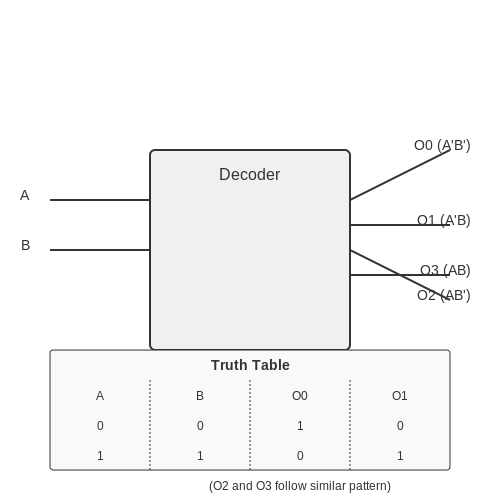
4.2 Interfacing Decoders with Logic Gates
Decoders play a crucial role in digital systems by converting coded information to a form comprehensible by other devices. Interfacing decoders with logic gates enhances their functionality, enabling complex operations based on input signals. In this section, we will delve into the intricate relationship between decoders and logic gates, exploring how these components work together seamlessly to execute diverse tasks in digital systems. We will examine the underlying principles, practical implementations, and real-world applications of this integration.Logical Operations with Decoders and Logic Gates
Decoders rely on logical operations to decode input signals and produce corresponding outputs. By interfacing decoders with logic gates, we can perform a wide array of operations, such as combining multiple decoders to create more complex decoding schemes. When connecting decoders to logic gates, it's crucial to consider the logical functions that each component performs. Logic gates, including AND, OR, NOT, and XOR gates, can be strategically integrated with decoders to achieve specific functionalities based on the system requirements.Implementation and Design Considerations
The seamless integration of decoders with logic gates requires meticulous design and implementation considerations. Understanding the logical relationships between decoders and various types of logic gates is essential for optimizing system performance and efficiency. By carefully configuring the connections between decoders and logic gates, engineers can create bespoke circuits tailored to specific applications. This customization allows for the efficient execution of tasks ranging from data processing to signal routing within digital systems.Real-World Applications
The interfacing of decoders with logic gates finds extensive application across diverse industries and disciplines. From controlling address lines in memory units to facilitating data transmission in communication systems, this integration plays a vital role in modern technological advancements. The use of decoders and logic gates in tandem enables the seamless operation of digital devices, paving the way for enhanced functionality and performance. Through innovative applications and strategic integration, engineers can harness the power of decoders and logic gates to drive groundbreaking solutions in various fields.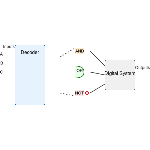
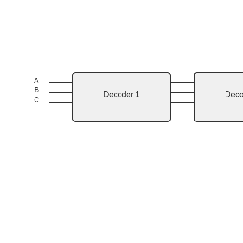
Cascade Configuration of Decoders
In complex digital systems, multiple decoders can be cascaded to achieve more intricate decoding functions. Cascading decoders involves interconnecting the outputs of one decoder to the inputs of another, enabling the system to manage a larger range of input combinations.
Unlike a single decoder that converts N inputs to 2^N outputs, cascading multiple decoders increases the overall decoding capacity of the system. This configuration is particularly useful in applications where the input space requires a higher degree of granularity.
Cascading decoders allows for efficient handling of larger sets of data or control signals by subdividing the decoding process into smaller, more manageable steps. Each decoder in the cascade processes a subset of the input space, distributing the computational load across the system and enhancing overall performance.
The total number of outputs in a cascade configuration is the product of the number of outputs of each individual decoder. This multiplication principle demonstrates the exponential increase in output possibilities as more decoders are cascaded together.
Cascading decoders is a powerful technique in digital system design, offering versatility in handling complex input scenarios. It is commonly used in address decoding circuits, data multiplexing, and signal routing applications where efficient translation of input signals is crucial.
5. System Integration in Robotics and Automation
System Integration in Robotics and Automation
Advanced-level readers like engineers, physicists, researchers, and graduate students often encounter complex challenges in robotics and automation systems. These challenges require a deep understanding of encoders and decoders for successful system integration. In this section, we delve into the foundational concepts and practical applications of these critical components in advanced robotics and automation.Understanding Encoders and Decoders
Encoders and decoders play pivotal roles in translating physical quantities into digital signals and vice versa within robotics and automation systems. Encoders convert mechanical motion into electrical signals, enabling precise control and feedback mechanisms. Simultaneously, decoders interpret digital signals to provide actionable data for system operations. Encoders come in various types, such as optical encoders, magnetic encoders, and capacitive encoders, each with specific advantages and applications based on the system requirements. Understanding the principles behind different encoder technologies is crucial for selecting the most suitable option for a given application.Applications in Robotics and Automation
The integration of encoders and decoders in robotics and automation systems opens up a myriad of practical applications. These components are essential in robotic arm positioning, automated conveyor belt control, precision motion control in manufacturing processes, and autonomous vehicle navigation. For instance, in robotics, encoders play a vital role in determining joint angles, velocity, and position feedback for robotic manipulators. Decoders, on the other hand, are essential for interpreting digitized information from encoders to enable intelligent decision-making and control algorithms.Case Study: Encoders in Autonomous Vehicles
One compelling real-world application of encoders in robotics is their use in autonomous vehicles. Encoders integrated into the vehicle's motor systems provide precise feedback on wheel rotation, enabling the vehicle to accurately navigate, maintain speed, and adjust trajectory in response to external stimuli. By analyzing the encoder data, the vehicle's onboard computer can make informed decisions regarding acceleration, steering angles, and obstacle avoidance strategies. This highlights the critical role encoders play in ensuring the safe and efficient operation of autonomous vehicles in dynamic environments.Advanced Mathematical Analysis
To achieve optimal performance in robotic systems, engineers often delve into advanced mathematical analyses of encoder signals. This may involve signal processing techniques, Fourier analysis for signal decomposition, and control theory to design robust feedback control strategies based on encoder data. Mathematical derivations underpin many aspects of encoder and decoder design, from understanding resolution and accuracy to implementing sophisticated closed-loop control algorithms. By harnessing mathematical principles, engineers can optimize system performance and enhance the capabilities of robotic and automation systems.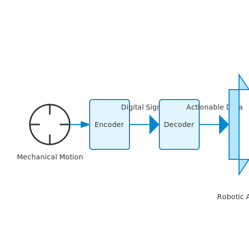
5.2 Data Communication Applications
In the realm of data communication, Encoders and Decoders play a crucial role in various advanced applications. These components are fundamental in transforming and interpreting signals to enable smooth communication between different devices and systems. ###Application in Telecommunications
One significant application of encoders and decoders is in telecommunications systems. In these systems, encoders are utilized to convert analog audio signals into digital formats for transmission over communication networks. Decoders at the receiving end then interpret these digital signals back into analog audio for playback. ###Usage in Digital Data Storage
Encoders and decoders are also instrumental in digital data storage applications. For instance, encoders are employed to convert data bits into suitable formats for storage, and decoders perform the reverse operation during data retrieval. This facilitates efficient data storage and retrieval processes. ###Role in Image and Video Compression
In multimedia applications, encoders and decoders play a pivotal role in image and video compression techniques. Encoders are used to compress multimedia data for efficient transmission and storage, while decoders at the receiving end reconstruct the compressed data for display or playback. ###Applications in Industrial Automation
In industrial automation settings, encoders and decoders are utilized for precise control and feedback mechanisms. Encoders provide accurate position and speed feedback for motor control systems, while decoders interpret these signals to ensure smooth operation of various automated processes. ###Integration in Electronic Communication Protocols
Moreover, encoders and decoders are integrated into electronic communication protocols to ensure reliable and secure data transmission. These components play a critical role in encoding and decoding data packets to facilitate error detection and correction in communication networks. This comprehensive utilization of encoders and decoders showcases their versatility and importance across a wide range of data communication applications, emphasizing their indispensable role in enabling efficient and effective communication between interconnected systems and devices.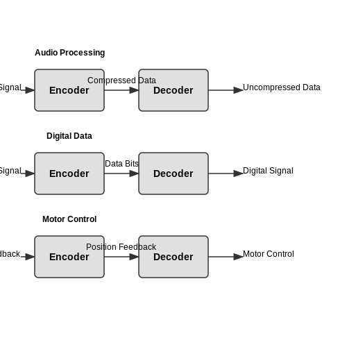
5.3 Use Cases in Control Systems
In the realm of control systems, encoders and decoders play crucial roles in various applications, enabling precise feedback mechanisms and efficient signal processing. Let's delve into some advanced use cases where these components shine:1. Robotics and Automation
Robotic systems heavily rely on encoders for accurate positioning and motion control. Incremental encoders track the movement of robotic arms, ensuring precise navigation and alignment in industrial settings. Decoders interpret these signals, facilitating real-time adjustments and enhancing overall operational efficiency.2. Aerospace and Avionics
In aerospace applications, encoders are utilized in flight control systems to provide critical feedback on aircraft components' positions and velocities. Decoders process this data to maintain stability, adjust flight trajectories, and ensure safe operation during various flight phases. The high reliability and precision of these devices are paramount in avionics.3. Medical Equipment
Medical devices such as MRI machines and surgical robots integrate encoders to deliver accurate diagnostic imaging and precise movements during procedures. Decoders in medical equipment interpret encoder signals to enable intricate surgical maneuvers, enhancing both patient outcomes and procedural safety.4. Automotive Industry
In the automotive sector, encoders and decoders are essential components in vehicle control systems. Encoders monitor wheel speeds, steering angles, and engine parameters to optimize performance, ensure stability control, and enhance overall driving experience. Decoders process this data to execute rapid responses, contributing to vehicle safety and efficiency.5. Renewable Energy Systems
Renewable energy installations, such as wind turbines and solar tracking systems, utilize encoders to monitor blade positions, solar panel angles, and energy production levels. Decoders in these systems translate encoder feedback into precise adjustments, maximizing energy generation efficiency and ensuring optimal operational performance. By leveraging the capabilities of encoders and decoders in these diverse sectors, control systems can achieve greater accuracy, reliability, and functionality, driving advancements across various technological domains.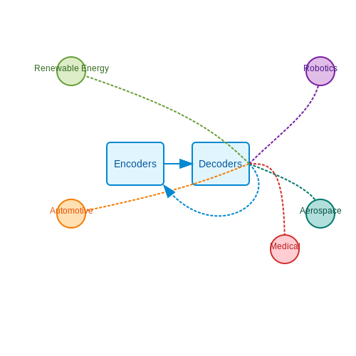
6. Accuracy and Resolution Issues
6.1 Accuracy and Resolution Issues
When considering encoders and decoders, it is crucial to delve into the concepts of accuracy and resolution. These parameters play a significant role in the efficacy and precision of these devices. Let's explore in detail how accuracy and resolution impact the functionality of encoders and decoders.
Accuracy in Encoders and Decoders
Accuracy in the context of encoders and decoders refers to how closely the output signal matches the actual input or desired signal. It is a measure of the device's ability to provide a correct output under specific operating conditions. The accuracy of an encoder or decoder is influenced by various factors such as mechanical tolerances, electrical noise, signal processing algorithms, and environmental conditions.
Mathematically, accuracy can be defined as:
High accuracy is essential in applications where precise position or data is required, such as robotics, CNC machines, or instrumentation systems. Manufacturers often specify the accuracy of encoders and decoders in terms of percentage error or number of bits.
Resolution in Encoders and Decoders
Resolution refers to the smallest change in input quantity that can be detected by an encoder or decoder. It determines the device's ability to discern fine details or incremental changes in the input signal. A higher resolution means that the device can provide more precise and detailed output information.
The resolution of an encoder or decoder is typically defined in terms of the number of discrete levels or bits in the output signal. For example, a 12-bit encoder can produce \(2^{12} = 4096\) unique output values. The resolution can also be expressed as the smallest angular or linear displacement that the device can detect.
Impact of Accuracy and Resolution
The accuracy and resolution of encoders and decoders are crucial factors that directly impact the overall performance and reliability of systems employing these devices. High accuracy ensures that the output signal closely matches the input, reducing errors and improving system precision. On the other hand, high resolution enables the device to capture fine details and subtle changes in the input signal, enhancing the system's sensitivity and responsiveness.
Engineers and designers must carefully consider the trade-offs between accuracy and resolution based on the specific requirements of the application. Balancing these factors is essential to achieve optimal performance and efficiency in various real-world scenarios.
6.2 Signal Noise and Interference
Signal noise and interference are critical aspects to consider in the design and function of encoders and decoders. Noise refers to any unwanted interference or fluctuations that can distort the original signal, affecting the accuracy and reliability of the encoded information. Interference, on the other hand, arises from external sources and can corrupt the signal during transmission or processing.Understanding Signal Noise
Signal noise can originate from various sources, including thermal noise, shot noise, flicker noise, and environmental factors. Thermal noise, also known as Johnson-Nyquist noise, is generated by the random movement of electrons in a conductor due to thermal energy. Shot noise results from the discrete nature of electric charge, causing fluctuations in current. Flicker noise, or 1/f noise, is prevalent in components like resistors and arises from material imperfections. Environmental noise includes electromagnetic interference (EMI) from external devices and radio frequency interference (RFI) from wireless transmissions.Mitigating Signal Noise
To reduce the impact of noise on signals, engineers employ various techniques such as shielding, filtering, and modulation. Shielding involves enclosing sensitive components in materials that block or absorb external interference. Filtering uses electronic circuits to remove specific frequency components of noise. Modulation alters the signal characteristics to embed the information within a specific frequency range, making it less susceptible to interference.Dealing with Interference
Interference can disrupt signal integrity by superimposing unwanted signals on the original data. Common interference types include crosstalk, where signals bleed between conductors, and electromagnetic interference from nearby electrical devices. To combat interference, differential signaling can be utilized, where the signal is transmitted as the voltage difference between two wires, reducing the impact of external disturbances. By understanding the nature of signal noise and interference, engineers can design robust encoding and decoding systems that maintain signal fidelity in challenging environments. --- If further exploration is needed on signal noise and interference, refer to the following resources:- Understanding Noise Sources and Effects — An in-depth look at the various sources of noise in electronic systems and their impact on signal integrity.
- Signal-to-Noise Ratio Explained — A detailed explanation of signal-to-noise ratio and its significance in communication systems.
- Introduction to Noise Figure — An introductory guide to noise figure and its role in amplifier performance.
6.3 Power Consumption Considerations
Power consumption is a critical aspect to consider in the design and implementation of encoders and decoders, particularly in modern electronic systems where energy efficiency is paramount. Understanding and optimizing power consumption not only improves the overall performance of these components but also plays a significant role in extending the operational life of battery-powered devices.Power Consumption in Encoders
In encoders, power consumption primarily depends on factors such as the operational frequency, output loading conditions, and the technology used in their construction. Generally, the power dissipated in an encoder can be calculated as the product of the supply voltage and the total current drawn by the device.- Pencoder is the power dissipation in the encoder
- Vsupply is the supply voltage
- Itotal is the total current drawn by the encoder
Power Consumption in Decoders
Decoders, on the other hand, play a crucial role in converting encoded data back to its original form. The power consumption of decoders is influenced by factors such as the complexity of decoding algorithms, the number of inputs, and the output loading conditions. Similar to encoders, the power dissipated in a decoder can be calculated as the product of the supply voltage and the total current drawn by the device.Energy-Efficient Design Practices
To achieve optimal power consumption in both encoders and decoders, designers should consider the following practices:- Implementing voltage scaling techniques to match supply voltage with operational requirements
- Utilizing advanced low-power logic families such as CMOS (Complementary Metal-Oxide-Semiconductor)
- Employing clock gating and power gating methodologies to selectively disable unused components
- Leveraging advanced fabrication technologies like FinFET to reduce leakage currents
7. Books on Encoders and Decoders
7.1 Books on Encoders and Decoders
- Decoding RF Circuit Design — This book covers advanced aspects of RF circuit design, incorporating encoders and decoders, which is crucial for capturing and interpreting RF signals effectively.
- Digital Signal Processing: Principles, Algorithms, and Applications — Offers a detailed exploration of signal processing, featuring sections on digital encoders and decoders crucial for data transmission and error correction.
- The Coding Manual for Qualitative Researchers — Discusses the significance of coding mechanisms—both digital and analog—within qualitative research, providing insights into data encoding and decoding techniques.
- Electronic Design Automation for Integrated Circuits Handbook — Delivers comprehensive insights into hardware design, including the practical applications of encoders and decoders in automated circuit design workflows.
- Information Theory — Explores the theoretical foundations of information systems which include elaborate discussions on encoding and decoding processes.
- Error-Correcting Codes: A Mathematical Introduction — Details the role of encoding and decoding in the context of error-correcting codes, crucial for reliable data transmission in communication systems.
- Modern Digital and Analog Communication Systems — An authoritative text that addresses both theoretical and practical aspects of communication systems, with specific chapters dedicated to the workings of encoders and decoders.
7.2 Journal Articles and Papers
- Encoders and Decoders for Digital Communication — This paper discusses advanced architectures and algorithms for designing efficient encoders and decoders, focusing on their applications in error correction in digital communication systems.
- Review of Encoding and Decoding Techniques for Modern Electronics — An in-depth review of various encoding and decoding techniques, highlighting their operational principles and enhancements in modern electronic devices.
- A Study on Lossless Encoding and Decoding Methods — This article provides comprehensive insights into lossless encoding and decoding methods, emphasizing their statistical models and application in data compression.
- Encoder-Decoder Architectures for Deep Learning Applications — Explores the role of encoder-decoder architecture in deep learning models, examining breakthroughs in autoencoders and their applications across various domains.
- Advancements in Quantum Encoding and Decoding — Offers insights into quantum encoding strategies and decoding processes, with a focus on recent advancements and potential future applications in quantum computing.
- Error Control Techniques in Encoders and Decoders — Discusses error correction techniques integrated into encoder-decoder systems, essential for improving data integrity in telecommunications.
- Optical Encoders and Decoders for Data Transmission — Focuses on the design and application of optical encoders and decoders, addressing their importance in increasing the efficiency of data transmission over optical networks.
7.3 Online Resources and Tutorials
For advanced-level readers interested in deepening their understanding of encoders and decoders, a thorough grasp of both theoretical and practical dimensions is essential. Here is a curated list of high-quality online resources that offer comprehensive tutorials, in-depth articles, and interactive content to enhance your knowledge in this area.
- An Overview of Encoder Technologies - Digi-Key — This resource offers a detailed insight into various encoder types, including their applications, operating principles, and selection criteria. It's ideal for engineers looking to integrate encoders into electronics design.
- Decoder and Encoder Circuits - EDN Network — Provides an advanced look at the design and operation of decoders and encoders, complete with circuit diagrams and analysis, which is beneficial for those involved in circuit design.
- Decoders and Multiplexers - Electronics Tutorials — Contains a series of tutorials that cover decoder functionality, types, and applications, supplemented with example circuits and Boolean expressions.
- Digital Circuits - Encoders - TutorialsPoint — Discusses the fundamentals of encoder circuits with emphasis on priority encoders and binary encoders, perfect for graduate students needing a robust theoretical foundation.
- Encoders and Decoders - Microcontrollers Lab — Explores practical applications of encoders and decoders in microcontroller projects and automation systems. It also includes tutorials on interfacing with various microcontrollers.
- Encoder and Decoder Basics - YouTube — A video tutorial that provides a visual and auditory explanation of encoder and decoder basics, making it an excellent supplement to textual content for visual learners.
- How Digital Encoders Work - Circuits Geek — Offers an in-depth analysis of digital encoding techniques, exploring both hardware logic design and signal processing applications.
- Understanding Encoders - EE Times — Delivers a comprehensive article on encoder technology advancements, focusing on new designs and their implications for robotics and industrial applications.
These resources provide a breadth of knowledge that is both practically relevant and theoretically robust, ensuring that you can apply the concepts of encoders and decoders effectively across various projects and research activities.