DC-DC Converters
1. Definition and Purpose
1.1 Definition and Purpose
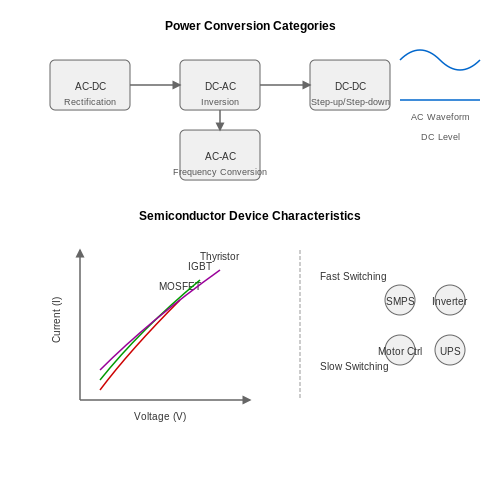
DC-DC converters are pivotal in the field of electronics, serving the essential role of converting direct current (DC) electrical energy from one voltage level to another. This process allows for more efficient power management and energy transfer across various electronic systems. With their ability to step up (boost) or step down (buck) voltage levels, these converters enable the optimization of battery performance, power supply regulation, and system integration in diverse applications, ranging from portable devices to large-scale industrial systems.
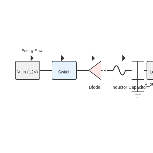
At their core, DC-DC converters employ various techniques—using inductors, capacitors, and switches—for controlling energy flow and enabling the transformation of voltage levels. The primary operating principles involve the principles of energy storage, electromagnetic induction, and switching behavior. Understanding these underlying principles is crucial for designing converters that meet specific efficiency, size, and voltage requirements.
The Need for DC-DC Converters
The necessity of DC-DC converters can be distilled into several key reasons:
- Voltage Regulation: They maintain a constant output voltage, crucial for protecting sensitive electronic components from voltage fluctuations.
- Power Efficiency: By optimizing voltage levels, they enhance overall system efficiency, which is especially important in battery-operated devices.
- Size and Integration: Enabling smaller circuit designs by allowing various components to operate at their optimal voltages.
As efficiently managing power becomes increasingly important in modern electronics, the role of DC-DC converters has expanded significantly. Their applications can be found in numerous devices, including consumer electronics, electric vehicles, and renewable energy systems. They are instrumental in maximizing battery life and performance, making them indispensable in today’s technology landscape.
Types of DC-DC Converters
In the realm of DC-DC converters, there are primarily three types, each suited for different applications:
- Buck Converter: Also known as a step-down converter, it reduces the input voltage to a lower output voltage. It is widely used in scenarios where the load requires less voltage than the source, contributing to efficiency in power management.
- Boost Converter: This type elevates the input voltage to a higher output voltage. It is particularly useful when the source voltage is lower than the required output voltage, such as in batteries powering higher voltage devices.
- Buck-Boost Converter: Combining both functions, this converter can either step-up or step-down the voltage. It is ideal for applications where the output voltage needs to maintain a specified level, regardless of variations in input voltage.
Each converter type utilizes different topologies and control mechanisms, allowing engineers to select the most appropriate design for a specific application. The versatility and functionality of DC-DC converters make them essential for optimizing energy use in a plethora of electronic systems.
Practical Applications
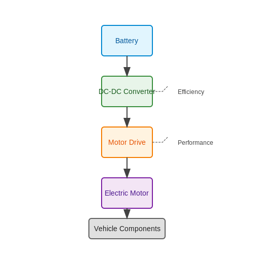
The influence of DC-DC converters permeates many sectors. In telecommunications, for instance, they are used in power supply circuits to ensure that voltage levels are kept stable amid fluctuating load conditions. In electric vehicles, DC-DC converters manage the power distribution from batteries to various components, enhancing energy efficiency and facilitating regenerative braking. Renewable energy applications also leverage these converters to adjust and optimize the output from solar panels or wind turbines to match the grid requirements.
With advancements in technology, ongoing innovations in converter design are poised to further enhance efficiency, reduce size, and improve performance. Thus, mastering the concepts surrounding DC-DC converters is crucial for any electronics professional aiming to remain at the forefront of technological development.
1.2 Basic Operation Principles
DC-DC converters are essential components in modern electronics, enabling efficient conversion of direct current (DC) voltages from one level to another. Understanding the basic operation principles behind these converters allows engineers and researchers to optimize their designs for specific applications, enhancing efficiency and performance.
At their core, DC-DC converters operate based on the principles of energy storage and transfer, utilizing various electrical components, such as inductors, capacitors, diodes, and switches. The two most prevalent types of DC-DC converters are step-up (boost) converters, which increase voltage, and step-down (buck) converters, which decrease voltage. Their operation is centered around the principles of switching and energy conservation.
Energy Storage and Switching
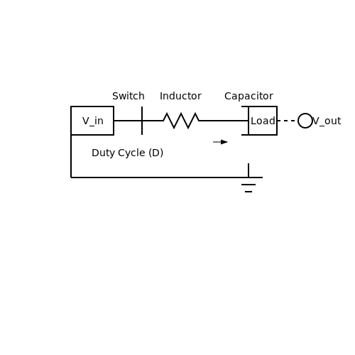
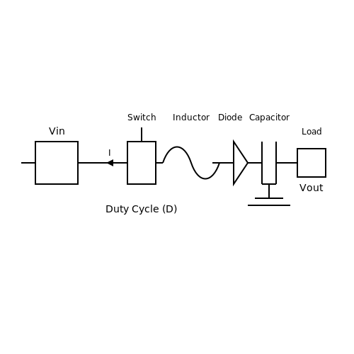
DC-DC converters leverage inductive and capacitive components to store and release energy. In a typical switching converter, when the switch (e.g., a transistor) is closed, current flows through the inductor, leading to an increase in energy stored in its magnetic field. When the switch is opened, this stored energy is transferred to the output side through a diode that allows current to flow in one direction only. The energy transfer process is periodic, governed by the duty cycle, which is the ratio of the on-time to the total period of the switch's operation.
For mathematical clarity, let's define the relationship between voltage and duty cycle. In the case of a boost converter, the output voltage \( V_o \) can be derived based on the input voltage \( V_{in} \) and the duty cycle \( D \) as follows:
Conversely, for a buck converter, the output voltage is determined by the same principles, yielding:
These pivotal equations represent a significant simplification of the behavior of DC-DC converters, emphasizing the crucial role of the duty cycle in determining the efficiency and performance of the converter.
Continuous and Discontinuous Modes of Operation
DC-DC converters can operate in two primary modes: continuous and discontinuous. Understanding the distinction between these modes is vital for practical applications. In continuous mode, the inductor current never falls to zero during the switching cycle, which typically occurs under higher load conditions. In contrast, in discontinuous mode, the inductor current does drop to zero at part of the switch cycle, often seen in lower load conditions.
This difference impacts the design considerations, as converters operating in discontinuous mode may require additional control strategies to maintain output voltage and reduce ripple. In real-world applications, such as power supply design for battery-operated devices, these modes, along with efficiency considerations, shape the converter's architecture and component selection.
Practical Applications and Relevance
The versatility of DC-DC converters allows them to be employed in a myriad of applications ranging from simple battery chargers to complex power management systems in electric vehicles and renewable energy systems. For example, in photovoltaic systems, DC-DC converters optimize the energy harvest from solar panels, enabling efficient use of the generated power to charge batteries or supply energy to the grid.
As technology continues to evolve, the importance of DC-DC converters grows, particularly in the quest for higher efficiency and smaller circuit footprints. Understanding the fundamental operation principles is essential for engineers designing these devices, as they must navigate complex requirements regarding efficiency, thermal performance, and load regulation.
Through a deep comprehension of the basic operation principles behind DC-DC converters, engineers and researchers are better equipped to innovate and adapt to the challenges presented in today’s rapidly evolving technological landscape.
1.3 Types of DC-DC Converters
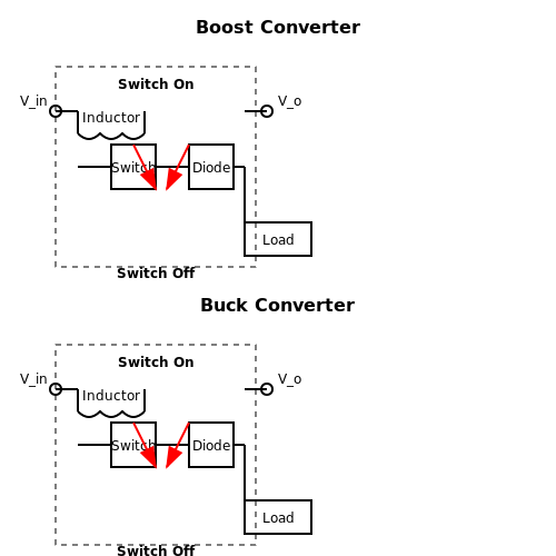
Understanding the various types of DC-DC converters is fundamental for engineers and researchers working across multiple fields such as renewable energy, telecommunications, and electric vehicle design. The two primary categories of DC-DC converters are buck converters and boost converters, each designed to convert input voltage to a different output voltage, catering to different applications.Buck Converters
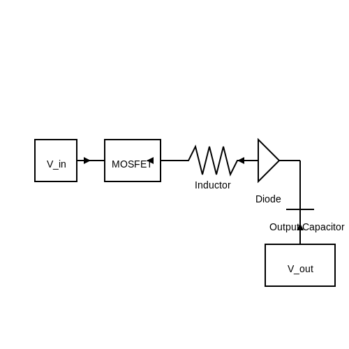
A buck converter is utilized to step down the voltage from a higher level to a lower level. This type of converter operates using a switch (typically a MOSFET), a diode, an inductor, and a capacitor. The fundamental operation can be explained using the following circuit diagram: 1. When the switch is closed, the input voltage \(V_{in}\) charges the inductor \(L\) and the output capacitor \(C\), leading to a buildup of energy in the inductor. 2. When the switch is open, the energy stored in the inductor is transferred to the load through the diode, resulting in a lower output voltage \(V_{out}\). The output voltage of a buck converter can be derived from the duty cycle \(D\) (the ratio of the on-time of the switch to the total time period). The relationship is described by the equation:Boost Converters
In contrast, a boost converter functions to step up the input voltage to a higher output voltage. It employs a similar switching mechanism but operates differently: 1. When the switch is closed, the inductor \(L\) stores energy from the input voltage \(V_{in}\). 2. When the switch is opened, the inductor releases its stored energy to the output, resulting in a higher voltage \(V_{out}\). The relationship for the output voltage of a boost converter is expressed through the duty cycle \(D\) as follows:Buck-Boost Converters
The buck-boost converter merges the functionalities of both buck and boost converters, enabling either voltage step-up or step-down capabilities. This versatility is achieved through a topology that allows for different arrangements of components. The output voltage can be either greater or smaller than the input voltage, expressed by the relationships: 1. When in buck mode:Real-World Applications
DC-DC converters play an essential role in modern electronics. For instance: - Power Supplies for Electronic Devices: Buck converters are favored for supplying power from batteries to microcontrollers, enhancing operational efficiency. - Renewable Energy: Boost converters are crucial in solar power systems to increase the voltage supplied to the grid or battery storage. - Electric Vehicles: Buck-boost converters enable wide-ranging voltage outputs, accommodating different parts of the vehicle's electrical system. Understanding these various types of DC-DC converters not only aids in designing more efficient electronic systems but also paves the way for innovations in energy consumption and sustainability.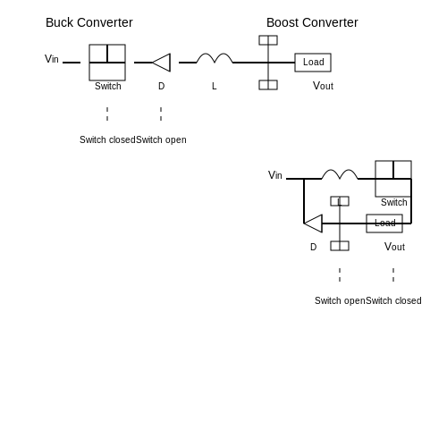
2. Working Principle
DC-DC Converters: Working Principle
DC-DC converters are pivotal components in modern electronics, enabling the conversion of direct current (DC) electrical energy from one voltage level to another. The fundamental working principle of these converters lies in their ability to modulate an input voltage, thereby facilitating efficient power management in a wide range of applications, from renewable energy systems to portable electronic devices.
At their core, DC-DC converters operate on the principle of energy transfer through inductive and capacitive components. They can be categorized based on their methods of operation: step-up (boost) converters, which increase voltage; step-down (buck) converters, which decrease voltage; and buck-boost converters, which can either increase or decrease the voltage depending on the requirements of the load. Understanding these fundamental types will pave the way for a deeper grasp of the specific mechanisms at play.
Basic Operation of DC-DC Converters
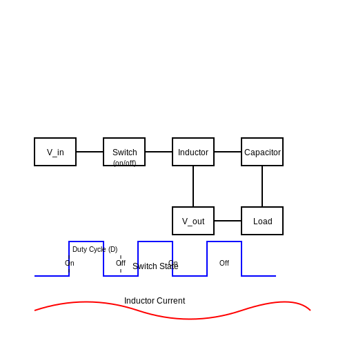
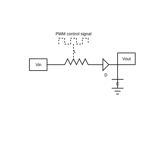
The operation of any DC-DC converter typically revolves around switching control. An electronic switch, often a transistor, is turned on and off at high frequency, creating pulses of energy that are then processed through an inductor or capacitor. This pulse-width modulation (PWM) technique allows for precise control of the output voltage and current:
- Inductor-Based Storage: In a buck converter, when the switch is on, current flows through the inductor, storing energy in its magnetic field. When the switch is turned off, the inductor opposes the change in current and releases energy to the load.
- Capacitor-Based Filtering: In addition to inductors, capacitors smooth the output voltage, filtering out fluctuations caused by the rapid switching of the electronic switch.
This back-and-forth transfer between energy stored in inductive and capacitive components is what allows DC-DC converters to efficiently manipulate voltage levels. The switching frequency, duty cycle (the ratio of the on time of the switching element to the total cycle time), and component values determine the conversion efficiency and performance characteristics.
Mathematical Foundations
To grasp how these concepts translate into practical scenarios, we will derive the relationship that governs the operation of a basic buck converter. The output voltage Vout can be expressed relative to the input voltage Vin as follows:
During the "on" phase of the switching cycle, the relationship can be described as:
where D is the duty cycle (0 < D < 1). In the "off" phase, the inductor discharges into the load, maintaining the output voltage based on stored energy. By varying D, one can effectively control Vout.
Real-World Applications
The benefits of DC-DC converters extend into numerous sectors, including:
- Consumer Electronics: Mobile phones and laptops utilize these converters to efficiently manage power and engage different voltage levels for various components, enhancing battery life.
- Renewable Energy Systems: Solar panels employ DC-DC converters to regulate output voltage levels for optimal energy harvesting and storage in batteries.
- Electric Vehicles: These systems incorporate DC-DC converters to convert battery voltage to the appropriate levels necessary for operation of motors and electronic systems.
In conclusion, understanding the working principle of DC-DC converters is essential not only for theoretical knowledge, but also for practical engineering applications. The efficiency and flexibility they offer make them critical for any modern electronic system.
2.2 Circuit Design and Components
The design of DC-DC converters is a sophisticated process that requires a deep understanding of both electronic components and circuit theory. In this section, we will explore the key components that make up DC-DC converter circuits, including inductors, capacitors, diodes, and switching elements. We'll also discuss various configurations and topologies commonly used in DC-DC converters, along with their practical implications.
Key Components
The essential components of a DC-DC converter can be classified into four main categories:
- Switching Elements: Typically transistors (such as MOSFETs or IGBTs), these components control the energy transfer by switching on and off at high frequencies.
- Inductors: Used to store energy temporarily, inductors help regulate the output voltage by smoothing current variations.
- Capacitors: They play a crucial role in filtering the output voltage, minimizing ripple by providing energy storage and discharge capabilities during load changes.
- Diodes: These components allow current to flow in one direction, providing a path for the current when the switch is off. Schottky diodes are commonly used due to their fast recovery times and low forward voltage drops.
Basic Topologies
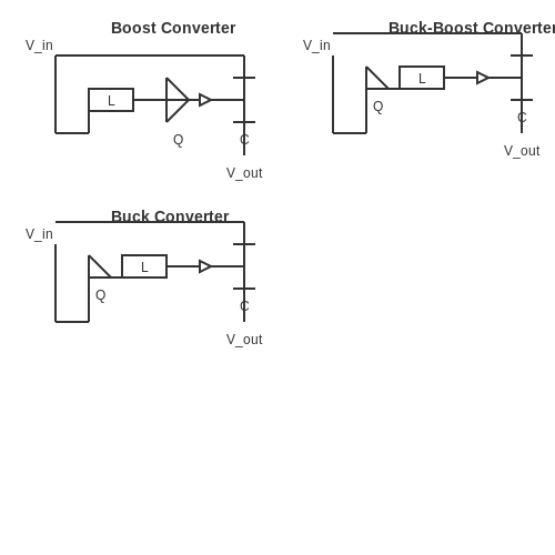
DC-DC converters can be categorized based on their topology, which determines how the components are arranged and how energy is transferred. The most common topologies include:
Boost Converter
A boost converter steps up the input voltage to a higher output voltage. It operates by storing energy in an inductor when the switch is closed and releasing it to the load when the switch opens. This can be expressed as follows:
Where \( D \) is the duty cycle of the switch. The boost converter is typically utilized in battery-powered applications that require higher voltage levels.
Buck Converter
Conversely, a buck converter steps down the input voltage to a lower output voltage. Similar to the boost converter, it stores energy in an inductor but releases it across a load to provide a lower voltage. The output voltage can be determined by:
This topology finds wide usage in power supplies and voltage regulation systems due to its efficiency and simplicity.
Buck-Boost Converter
The buck-boost converter can both step up and step down the voltage, which makes it flexible for various applications. The output voltage can be formulated as:
This topology is essential in applications where the input voltage may fluctuate above and below the desired output voltage.
System Optimization and Real-World Applications
In a practical context, optimizing a DC-DC converter involves careful consideration of thermal management, efficiency, and electromagnetic interference (EMI). Advanced control techniques, such as PWM (Pulse Width Modulation) and PFM ( Pulse Frequency Modulation), can further enhance performance. Key applications for DC-DC converters include:
- Power supplies in consumer electronics
- Renewable energy systems, such as solar power inverters
- Electric vehicles for battery management
- Industrial automation and control systems
Ultimately, a thorough understanding of circuit design and components is vital in creating efficient and reliable DC-DC converters capable of meeting the increasingly demanding energy requirements of modern electronic systems.
2.3 Efficiency Analysis
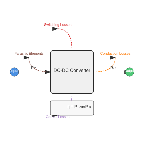
Understanding the efficiency of DC-DC converters is essential for optimizing performance and minimizing power losses. Efficiency is typically defined as the ratio of output power to input power and can be mathematically described by the equation:
Where:
- η is the efficiency percentage.
- Pout is the output power.
- Pin is the input power.
Key Factors Affecting Efficiency
The efficiency of DC-DC converters can be influenced by several factors:
- Switching losses: Occur during the transition of the switch from on to off states. Faster switching minimizes these losses but may increase electromagnetic interference (EMI).
- Conduction losses: Result from the resistance of the components. The voltage drop across these resistive parts contributes to power loss.
- Control losses: Associated with the control circuitry used to regulate the output voltage, which may also consume power.
Additionally, parasitic elements in circuit components, such as inductors and capacitors, can further degrade efficiency. Therefore, understanding and modeling these factors is crucial.
Practical Applications
High efficiency in DC-DC converters is particularly crucial in applications where power conservation is vital, including:
- Battery-powered devices: Such as smartphones and laptops, where efficiency prolongs battery life.
- Renewable energy systems: Like photovoltaic systems where maximizing power extraction is essential.
- Electric vehicles: Where energy efficiency directly translates to increased mileage.
Measurement Techniques
To accurately assess the efficiency of a DC-DC converter, precise measurement techniques must be employed. Typical methods include:
- Direct measurement: Using power analyzers to measure input and output currents and voltages directly.
- Indirect methods: Such as using thermal measurements to infer losses from temperature increases in components.
Each method has its advantages and inherently impacts the complexity and cost of tests. However, determining efficiency not only aids in optimizing the converter design but also plays a vital role in complying with regulatory requirements in various industries.
In conclusion, rigorous efficiency analysis of DC-DC converters is foundational in enhancing the performance of electronic systems. Engineers must continually evaluate and refine these systems within their specific application contexts to achieve optimal results.
2.4 Applications of Buck Converters
Buck converters, also known as step-down converters, play a crucial role in the field of power electronics due to their efficiency and versatility in reducing voltage levels with minimal energy loss. Their operation is based on storing energy in inductors and releasing it at a lower voltage, which not only improves energy efficiency but also extends battery life in various applications. Below, we delve into several key applications of buck converters that highlight their significance in contemporary technology.
Power Supply for Electronic Devices
One of the primary applications of buck converters is in the design of compact and efficient power supplies for handheld and portable electronic devices such as smartphones, tablets, and laptops. The need for higher battery efficiency has led engineers to develop power supply circuits that can convert the battery voltage to required levels without excessive heat generation. In these circuits, the buck converter achieves conversion rates above 90%, significantly improving energy savings and extending usage time.
DC Motor Control
Buck converters are frequently used in applications where direct current (DC) motors are utilized, especially in electric vehicles and robotics. By adjusting the output voltage and current, buck converters allow for precise control over the motor speed and torque. This is achieved through pulse-width modulation (PWM), where the converter adjusts the duty cycle, effectively managing the amount of voltage fed to the motor. This method enhances performance, prolongs motor life, and improves overall system responsiveness.
Consumer Electronics
In consumer electronics, buck converters are extensively used to convert higher voltages from wall adapters or power sources to lower voltages needed by internal circuits. Televisions, gaming consoles, and audio equipment utilize these converters to ensure that components receive stable and adequate power while operating efficiently. The modular nature of buck converters also facilitates their integration into various circuits without causing significant redesigns.
Renewable Energy Systems
With the global shift toward renewable energy, buck converters find integral applications in photovoltaics (solar panels) and wind energy systems. In these contexts, they serve to convert the fluctuating input voltages from solar cells or wind turbines to a stable output suitable for battery charging or grid integration. Their ability to handle variable input makes them especially valuable in these applications, where energy efficiency is paramount for maximizing power output.
Telecommunication Systems
Network infrastructure, including telecommunications, relies heavily on buck converters to power various devices such as routers, base stations, and signal processing units. Given the critical nature of these systems, buck converters are employed to provide reliable, noise-free power with high efficiency. Moreover, efficient power management ensures longer operational life for equipment and reduced operational costs.
Applications in Robotics and Automation
In robotics, precise control of power delivery is essential for the functioning of various sensors, actuators, and processing units. Buck converters play a pivotal role in supplying the required lower voltages to these components, enhancing the robot's control systems with reduced weight and increased efficiency. Similarly, in automated industrial applications, buck converters power PLCs (Programmable Logic Controllers) and other control hardware while optimizing the energy consumption of the overall system.
In conclusion, the versatility and efficiency of buck converters make them essential in a wide array of fields. Ranging from portable electronics to renewable energy systems, their ability to efficiently convert voltage levels is crucial for modern technological advancements. As the focus on energy efficiency continues to grow, the importance of buck converters is only set to rise, leading to further innovations and applications in the industry.
3. Working Principle
3.1 Working Principle
DC-DC converters are essential components in modern electronic systems, playing a critical role in power management by transforming a direct current (DC) voltage level to another. To fully appreciate the workings of these devices, it is necessary to explore the underlying principles that govern their operation.
Fundamentals of DC-DC Conversion
At the core of a DC-DC converter’s functionality is the principle of energy conversion, which can be illustrated using the law of conservation of energy. This principle posits that energy can be neither created nor destroyed; it can only be converted from one form to another. In the context of DC-DC converters, electrical energy is transformed as it moves through the converter, necessitating a thorough understanding of various circuit components.
DC-DC converters utilize semiconductor devices such as transistors, diodes, inductors, and capacitors to facilitate the voltage transformation. Depending on the topology, a converter can step down (buck converter) or step up (boost converter) the voltage. Furthermore, some converters can accomplish both functions in a single circuit (buck-boost converters). Understanding the basic operation of these elements is crucial to grasp how the converter maintains efficiency and stability.
Key Operating Principles
Most DC-DC converters operate through the process of switching. This method converts the input DC voltage to an AC signal, applies filtering, and converts it back to a desired DC voltage. To explain this mechanism, let's delve into a typical buck converter, which steps down the input voltage.
- Switching Element: The switching element, typically a MOSFET, rapidly alternates between ON and OFF states. This switching action controls the amount of energy transferred to an inductor during each cycle.
- Inductor: The inductor stores energy when the switch is ON and releases energy to the load when the switch is OFF. The energy stored in an inductor is given by the equation:
where \(E\) is energy, \(L\) is inductance, and \(I\) is current through the inductor.
- Diode: A diode directs current flow and prevents backflow when the switch is OFF, ensuring that the energy from the inductor flows to the output load.
- Output Capacitor: This component smooths the output voltage, mitigating fluctuations caused by switching, and stabilizes the output for the connected load.
Mathematical Modeling of Buck Converter
To derive the relationship between input and output voltages in a buck converter, we use the duty cycle \(D\) defined as the ratio of the ON time to the total switching period \(T\). Let \(V_{in}\) be the input voltage and \(V_{out}\) the output voltage:
where \(D\) ranges from 0 to 1. For an ideal buck converter, the output voltage is directly proportional to the input voltage and the duty cycle.
Practical Applications
DC-DC converters are ubiquitous in various applications, from power supplies in smartphones and laptops to electric vehicles and renewable energy systems like solar panels. Their ability to efficiently regulate voltage levels ensures optimal operation and extends the lifespan of electronic components.
In closing, the working principle of DC-DC converters embodies energy transformation facilitated by fundamental electrical components. Understanding these principles equips engineers and researchers with the tools to innovate in power management technologies, advancing applications across multiple sectors.
3.2 Circuit Design and Components
DC-DC converters are integral components in modern electronic systems, allowing for effective voltage regulation and power management in a variety of applications, from portable devices to large industrial systems. This section delves into the essential circuit design and the components that constitute effective DC-DC converters, focusing on practical implementations and theoretical foundations.
Understanding the Basic Topologies
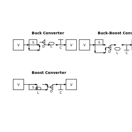
The design of a DC-DC converter typically starts with choosing an appropriate topology. The most common topologies include buck, boost, and buck-boost converters, each with unique characteristics:
- Buck Converter: Steps down the input voltage while increasing the current. It is widely used in battery-powered devices to prolong battery life by ensuring that devices only draw the power they need.
- Boost Converter: Steps up the input voltage while decreasing the current. Often used in applications where battery voltages are lower than required operating voltages, such as in certain LED drivers and solar power systems.
- Buck-Boost Converter: Can step up or step down the voltage depending on the input-output conditions. This versatility makes it valuable in renewable energy applications and scenarios where the input voltage can fluctuate significantly.
Key Components of a DC-DC Converter
To build a functional DC-DC converter, several key components are necessary:
- Inductor: Acts as an energy storage element. In buck and boost converters, the inductor helps manage current flow and reduces output voltage ripple. The selection of the inductor is critical, as it affects the efficiency and performance of the converter.
- Capacitor: Used at the input and output to filter voltage and stabilize the output. The capacitor selection impacts transient response and ripple voltage at the output.
- Switching Element (Transistor): Responsible for controlling the energy transfer from the input source to the output. MOSFETs are common due to their efficiency and fast switching capabilities.
- Diode: Provides a path for current when the switching element is off. Schottky diodes are often used for their low forward voltage drop and fast recovery times, which enhance overall efficiency.
- Control Circuitry: Regulates the output voltage by adjusting the duty cycle of the switching element. Techniques such as pulse-width modulation (PWM) are commonly used to achieve stable output voltage levels.
Regulating Output Voltage: Control Methods
The control method is critical for ensuring that the output voltage remains stable under varying load conditions. Two common control techniques include:
- Voltage-Mode Control: Monitors the output voltage and adjusts the duty cycle of the switching element to maintain the desired output level. It is simpler and often preferred in applications where fast transient response is not critical.
- Current-Mode Control: Monitors both output voltage and inductor current, enabling improved transient response and inherent current limiting. This method is more complex but offers better performance in demanding applications.
Design Considerations
When designing DC-DC converters, numerous factors must be taken into account to optimize performance:
- Efficiency: A critical factor, especially in battery-operated devices, where energy conservation is paramount. Efficiency is dictated by the choice of components and their arrangement within the circuit.
- Thermal Management: Key to ensuring reliability; adequate heat dissipation mechanisms must be employed, particularly for high-power converters.
- PCB Layout: Good layout practices are essential to minimize loop areas, reduce electromagnetic interference (EMI), and ensure stable operation under various conditions.
Real-world applications of DC-DC converters span across sectors, including renewable energy systems that regulate output voltage from solar panels, consumer electronics that require specific voltage levels for processors, and telecommunications, where power distribution is critical for signal integrity.
Understanding circuit design and the choice of components in DC-DC converters is vital for engineers aiming to enhance efficiency and performance in their designs. With the right tools and knowledge, one can leverage these circuits for a plethora of applications.
3.3 Efficiency Analysis
The efficiency of DC-DC converters is a critical parameter that dictates their performance in various practical applications, from power management in electronics to power supplies in renewable energy systems. Efficiency signifies how effectively a converter transforms input power into output power, and it is typically expressed as a percentage. Understanding the factors influencing efficiency and the methodologies for its analysis is essential for optimizing converter designs. At its core, the efficiency (\( \eta \)) of a DC-DC converter can be defined by the following equation:Loss Mechanisms in DC-DC Converters
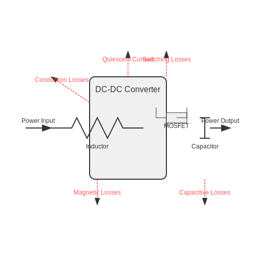
Understanding the primary sources of losses is pivotal for efficiency analysis. These losses can be broadly categorized into:- Conduction Losses: These occur when current flows through non-ideal components, leading to resistive heating. The losses can be modeled according to Ohm's Law, where I²R losses in the inductor and switch are significant.
- Switching Losses: During the transition between on and off states, energy is expelled in the form of heat due to non-instantaneous switching. This includes turn-on and turn-off losses.
- Magnetic Component Losses: Inductors and transformers exhibit core losses due to hysteresis and eddy currents, which can significantly lower efficiency, especially at high frequencies.
- Capacitive Losses: Equivalent series resistance (ESR) in capacitors also contributes to inefficiency, particularly affecting the transient response.
- Quiescent Current: This is the power consumed by the control circuitry in a converter while in idle state. Minimizing quiescent current can be crucial for battery-powered applications.
Methods for Analyzing Efficiency
Efficiency analysis can be approached through both experimental and simulation methods, each offering unique insights into converter performance:Experimental Methods
In practical implementations, measuring input and output power across various load conditions provides real-time data on efficiency. Instruments such as power analyzers can quantify losses by measuring voltage and current at distinct points in the circuit.Simulation Methods
Simulators like SPICE, or specialized software for power electronics such as PSIM or LTspice, allow engineers to model and analyze efficiency without the constraints and complexities of physical prototyping. These tools enable the exploration of design variations and their potential impacts on efficiency.Maximizing Efficiency in Design
When striving for maximum efficiency, several design strategies can be employed:- Optimizing Component Selection: Choosing low RDS(on) MOSFETs, specialized low-loss inductors, and capacitors with minimal ESR can drastically reduce conduction losses.
- Using Soft-Switching Techniques: Techniques such as Zero Voltage Switching (ZVS) or Zero Current Switching (ZCS) reduce switching losses by mitigating the energy expelled during transitions.
- Embedding Advanced Control Techniques: Utilizing digital control methods can facilitate improved regulation and allow for adaptive switching frequencies, which can enhance efficiency.
3.4 Applications of Boost Converters
Boost converters, which fall under the broader category of DC-DC converters, serve crucial roles across various industries and applications. Their ability to step up voltage levels allows for flexibility in power management and energy efficiency. This subsection dives into the multifaceted applications of boost converters, illustrating their significance in modern technology and renewable energy systems.Energy Harvesting
One of the most promising applications for boost converters is in the field of energy harvesting, particularly from renewable sources. For example, small solar panels, thermoelectric generators, or piezoelectric devices typically generate low voltages insufficient for practical use. A boost converter enables these devices to elevate the low output voltage to a usable level, making it possible to charge batteries or power small electronic devices efficiently. In such applications, the challenge often lies in maximizing the output power, which depends on the input voltage and current levels. Using Maximum Power Point Tracking (MPPT) algorithms in conjunction with boost converters can optimize energy extraction from solar panels.Battery-Powered Devices
Boost converters are widely used in battery management systems for portable electronic devices. Many modern devices, such as smartphones, tablets, and wearables, rely on lithium-ion batteries, which generally output voltages around 3.7 V. However, many components within these devices, like sensors or communication modules, require higher voltages to operate effectively. By integrating boost converters into the power circuitry, designers can ensure that the necessary voltage is reached while extending battery life. For instance, a boost converter can step up the voltage to 5 V or even higher, allowing the device to maintain performance without compromising energy efficiency.LED Drivers
In lighting applications, particularly with LEDs, boost converters are essential for driving the diodes efficiently. LEDs typically require a constant forward voltage, which varies depending on the color and construction. Since the supply voltage may not always match the required input, a boost converter can step up lower voltages from batteries or other sources to meet the precise needs of the LED. Moreover, engaging with dimming control through pulse-width modulation (PWM) techniques in combination with boost converters can provide an effective solution for consumable power regulation while enhancing the user experience by enabling light intensity adjustments.Electric Vehicles and Hybrid Systems
In the rapidly evolving sector of electric vehicles (EVs) and hybrid electric vehicles (HEVs), boost converters play a pivotal role in managing and utilizing power more efficiently. The ability to convert energy from low-voltage battery banks to higher voltages for use in drive motors is essential for maximizing vehicle performance. By effectively boosting voltage, these converters help optimize motor drive inputs, ensuring greater power efficiency, torque management, and overall system performance. Similarly, they can facilitate the integration of regenerative braking systems, where the energy generated during braking is converted and stored for later use, enhancing the vehicle's overall energy management strategy.Industrial Power Supplies
The industrial sector often requires reliable power supplies for various applications, including automation, control systems, and heavy machinery. Boost converters, due to their robustness and adaptability, are utilized in these environments to smooth power delivery and ensure that varying loads receive stable voltage levels. In older systems where voltage instability is a concern, retrofitting with boost converters allows for the extension of service life for legacy equipment, improving both operational reliability and efficiency.Conclusion
The significance of boost converters is evident in their wide-ranging applications across multiple sectors, including energy harvesting, portable electronics, lighting solutions, electric vehicles, and industrial power supplies. Their ability to increase voltage levels not only enhances system performance but also contributes to energy efficiency and sustainability efforts in technology today. As demands for power density and efficiency grow, the innovation and integration of boost converters will undoubtedly continue to play a central role in shaping future applications.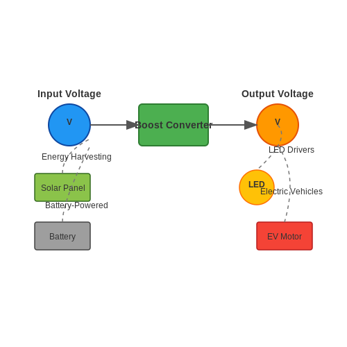
4. Working Principle
4.1 Working Principle
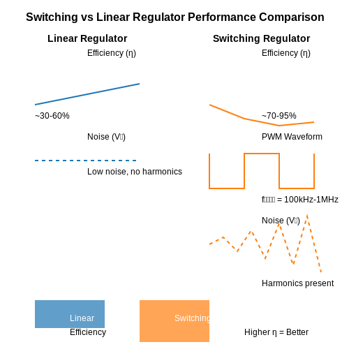
In the realm of electronics, DC-DC converters play a crucial role in converting direct current (DC) from one voltage level to another. This conversion is not only essential in power supply applications but is instrumental in optimizing the efficiency of electronic circuits. The fundamental working principle of DC-DC converters hinges on the conversion of voltage levels through principles of electromagnetic induction and energy storage, often utilizing inductors and capacitors. To understand how a DC-DC converter operates, one must first grasp the concept of switching regulators versus linear regulators. Switching regulators, which represent a major category of DC-DC converters, periodically switch a transistor on and off, thereby controlling the energy transfer to the output load. In contrast, linear regulators provide a steady output voltage by dissipating excess voltage as heat, resulting in lower efficiency, particularly for significant voltage drops. The operation of a switching DC-DC converter can typically be divided into four key stages: 1. Switching On: When a switch (often a transistor such as a MOSFET) is turned on, current flows through an inductor, causing it to store energy in the form of a magnetic field. This is described by Lenz's Law, where the direction of induced electromotive force opposes the change in current. 2. Energy Storage: While the switch is on, the inductor current increases linearly with time. The energy stored in the magnetic field of the inductor can be expressed mathematically as: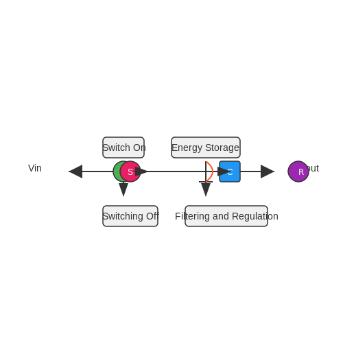
4.2 Circuit Design and Components
DC-DC converters play a crucial role in modern electronics by enabling voltage regulation and power conversion across various applications. The design of DC-DC converters involves careful selection of circuit components, configuration, and topology to achieve the desired performance specifications.
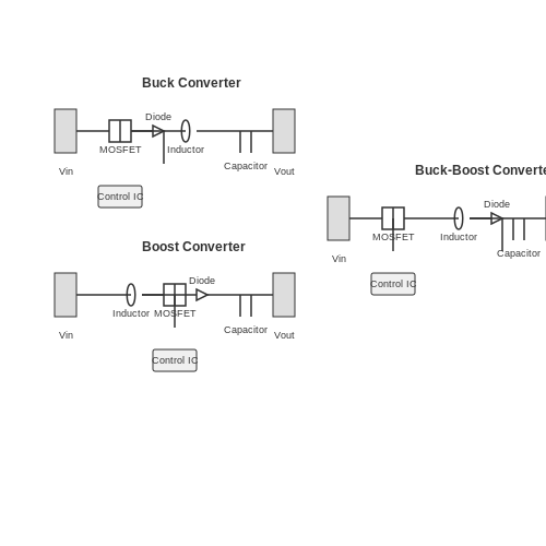
Understanding Circuit Topologies
The first step in designing a DC-DC converter is selecting an appropriate topology. The main types of DC-DC converters include buck, boost, and buck-boost converters:
- Buck Converter: This topology steps down an input voltage to a lower output voltage. It is commonly used in battery-powered devices to extend operational time.
- Boost Converter: This configuration increases the input voltage to a higher output voltage, which is useful in applications that require higher voltages from lower battery voltages.
- Buck-Boost Converter: This topology can either step up or step down the voltage, providing flexibility in power management.
Each of these topologies uses a combination of inductors, capacitors, and semiconductors to achieve desired voltage outputs. The selection of topology depends not only on the voltage requirements but also on factors such as load characteristics and efficiency.
Key Components in DC-DC Converters
A typical DC-DC converter circuit comprises several essential components, each playing a critical role:
- Inductors: Inductors are used to store energy and filter current in buck and boost converters. The inductance value must be carefully selected based on the desired current ripple and switching frequency.
- Capacitors: Capacitors smooth the output voltage and reduce ripple. The choice of capacitor type (ceramic, electrolytic, etc.) affects the transient response and overall performance.
- Switching Devices: Transistors (typically MOSFETs) act as switches to control the flow of energy. Their switching speed and on-resistance directly influence efficiency.
- Diodes: Used for current rectification, diodes must have low forward voltage drop characteristics to minimize losses.
- Control ICs: These integrated circuits manage the overall operation of the converter by regulating the output voltage, controlling the feedback mechanism, and ensuring system stability.
Design Considerations
When designing a DC-DC converter, engineers must consider several key factors that influence performance and reliability:
- Efficiency: Defined as the ratio of output power to input power, efficiency is critical in reducing heat generation and improving battery life.
- Thermal Management: As converters operate, they generate heat, which can degrade performance and cause component failure. Implementing heat sinks or cooling mechanisms may be necessary.
- Regulation: Voltage regulation must be maintained across varying load and input conditions. Engineers often use feedback control loops to attain this stability.
- Size and Weight: Especially in portable applications, minimizing space and weight while maintaining performance is essential.
Real-World Applications
DC-DC converters find wide-ranging applications across industries:
- Consumer Electronics: Devices like smartphones, laptops, and tablets rely heavily on efficient power management to optimize battery life and performance.
- Renewable Energy Systems: In solar power systems, DC-DC converters help manage energy conversion between solar panels and batteries.
- Automotive Systems: Modern vehicles utilize several low-voltage systems powered by DC-DC converters for efficient power distribution.
In conclusion, the circuit design of DC-DC converters is a multifaceted process that integrates a variety of components and design considerations. A thorough understanding of the principles governing each component and configuration informs effective, efficient designs suitable for the demands of modern electronics.
4.3 Efficiency Analysis
The efficiency of DC-DC converters is a critical parameter that influences their design, performance, and application in modern electronic systems. It is essential to quantify how much of the input power is utilized effectively in producing output power while minimizing losses due to factors such as heat, magnetic losses, and switching losses. Understanding these losses helps engineers optimize converter designs, leading to better performance and reliability in real-world applications. To begin with, efficiency (\( \eta \)) is defined as the ratio of output power (\( P_{out} \)) to input power (\( P_{in} \)). The basic formula representing efficiency is: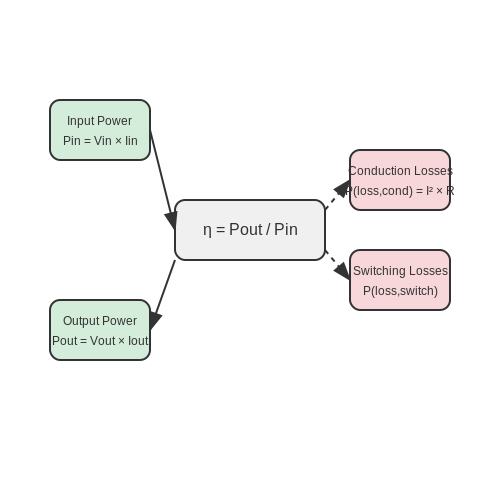
4.4 Applications of Buck-Boost Converters
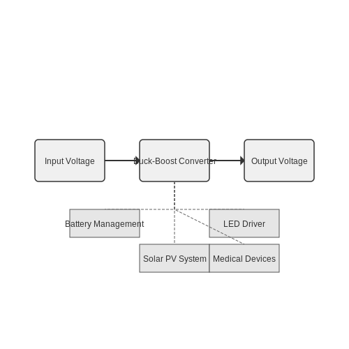
Buck-boost converters have emerged as a pivotal technology in the realm of power electronics, owing to their ability to not only step up (boost) but also step down (buck) voltage levels. Their dual capability allows for versatile applications, especially in scenarios where the input voltage may fluctuate above and below the desired output voltage. In this section, we will explore several advanced applications of buck-boost converters, highlighting their significance and real-world relevance.
Energy Storage Systems
One of the most critical applications of buck-boost converters is in energy storage systems, particularly in battery management. As the state of charge in batteries changes, so does their output voltage. Buck-boost converters enable constant voltage regulation, which is essential in ensuring that batteries are neither undercharged nor overcharged.
For instance, in electric vehicles (EVs), buck-boost converters help manage the power supply from the battery to the electric motor. This adaptability ensures optimal performance regardless of varying battery states, thus enhancing the efficiency and longevity of the battery. Moreover, integrating renewable energy sources such as solar panels into the grid often requires buck-boost converters to adjust the voltage levels to match the grid requirements.
Photovoltaic Systems
In solar photovoltaic (PV) applications, the output voltage can vary significantly with changes in sunlight intensity and temperature. To optimize energy harvesting, buck-boost converters are employed to maintain a stable output voltage that can be used for grid connection or battery charging.
For example, a buck-boost converter can ensure that a solar panel operates at its maximum power point, adapting to the fluctuating conditions of solar irradiance. By maintaining efficiency, these converters facilitate better energy capture and utilization, making solar energy systems more economically viable.
Portable Electronics and IoT Devices
In portable electronics and Internet of Things (IoT) devices, efficient power management is crucial. Buck-boost converters play a vital role in providing the necessary voltage levels for various components without compromising on size or weight. These converters allow devices to operate efficiently across different load conditions, thereby conserving battery life.
For example, in a wearable health monitor, the device may need a regulated 3.3V supply for its sensors while the battery voltage could vary between 2.5V and 4.2V as it discharges. A buck-boost converter can seamlessly adjust to supply the required voltage, ensuring accurate sensor readings and extending the operational time of the device.
LED Drivers
Illuminating various applications, LED drivers require consistent voltage and current for optimal performance and longevity. Buck-boost converters are integral in designing LED drivers that can handle varying supply voltages.
Consider street lighting applications where the input voltage can vary due to line losses or fluctuating supply levels. A buck-boost converter can maintain a constant current through the LEDs regardless of the supply conditions, ensuring consistent brightness and color output. This capability not only enhances the quality of lighting but also reduces the risk of LED failure caused by over-voltage or under-voltage scenarios.
Medical Devices
In the medical field, where precision is paramount, buck-boost converters are essential for powering devices like portable ultrasound machines or diagnostic equipment that require stable voltage levels for their sensitive components. The adaptability of buck-boost converters allows these devices to function efficiently even with varying battery levels.
Additionally, many portable medical devices benefit from the compact size and weight of buck-boost converters, which contribute to the overall portability necessary for applications in clinical settings or emergency situations.
Conclusion
In summary, buck-boost converters serve a multitude of applications, adapting to dynamic voltage conditions while ensuring system efficiency and reliability. As the demand for versatile power solutions continues to grow, the role of buck-boost converters in applications such as energy storage systems, renewable energy technologies, portable devices, LED drivers, and medical equipment becomes increasingly significant. Their ability to enhance both performance and energy efficiency is invaluable in modern technological contexts.
5. PWM Control
5.1 PWM Control
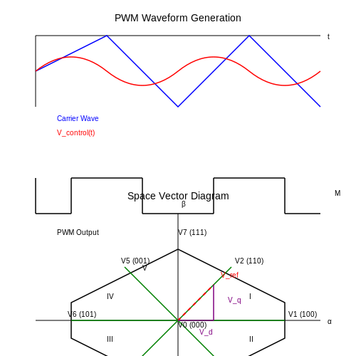
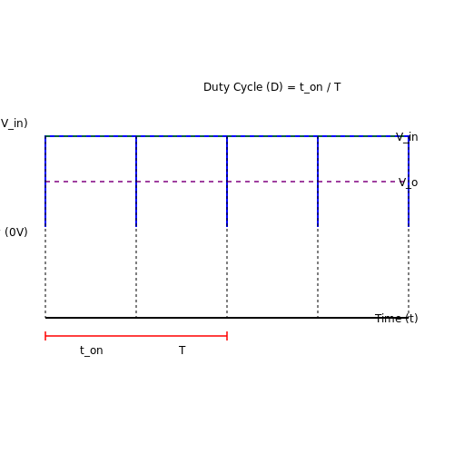
Pulse Width Modulation (PWM) is a vital technique employed in DC-DC converters to regulate the output voltage and current. Specifically, PWM achieves this by adjusting the duty cycle—essentially the proportion of the time the signal is in a high state compared to the low state. This functionality is crucial not only for maintaining the desired power levels but also for optimizing the efficiency of the entire system.
The principle behind PWM is straightforward yet powerful. When we talk about controlling a switch (often a transistor) in the converter, we can alternate its state between 'on' and 'off' rapidly. The average output voltage can be controlled by varying the ratio of the 'on' time to the total time of a switching period. In mathematical terms, if T represents the total period of one cycle and t_on is the time the switch is closed, the duty cycle D can be expressed as:
The average output voltage V_o from the PWM can be derived as:
Here, V_in refers to the input voltage of the converter. This means that by altering the duty cycle, the output voltage can be finely tuned to meet the requirements of the load efficiently.
Real-World Applications of PWM in DC-DC Converters
PWM is prevalent in various applications thanks to its flexibility and effectiveness. For instance, in power supplies for computer systems, PWM enables rapid adjustments in voltage, ensuring that components are provided with precisely what they need, thereby preventing damage from overvoltage or insufficiency. Additionally, in electric vehicles, PWM is utilized to control traction motor speed, maximizing energy conservation while optimizing performance.
Furthermore, PWM's role extends into renewable energy systems, such as solar inverters. In this context, the technique can effectively manage the grid connection by adjusting output based on fluctuating power production from solar panels, thereby stabilizing energy flux and improving system reliability.
Implementing PWM Control
The implementation of PWM control in a DC-DC converter can be achieved through both analog and digital methods. Analog PWM involves using components like operational amplifiers and comparators, which can vary the duty cycle based on the given reference voltage. On the digital side, microcontrollers or digital signal processors (DSPs) are often employed. These devices can generate precise PWM signals with the help of timers and enable sophisticated control algorithms that adjust the output based not only on voltage feedback but also on current and thermal conditions.
For practical PWM implementation, it is essential to consider the trade-offs between switching frequency, system size, and efficiency. Higher switching frequencies can yield smaller components, yet they can also lead to increased switching losses and electromagnetic interference (EMI), which might necessitate additional filtering techniques.
Ultimately, selecting the appropriate PWM control scheme involves an intricate balance of these factors, and careful design considerations must be made to optimize the performance of the DC-DC converter for its intended application.
5.2 Voltage Mode Control
Voltage mode control is a fundamental technique employed in the operation of DC-DC converters, particularly in the realm of switched-mode power supplies (SMPS). This method focuses on regulating the output voltage of a converter by manipulating the duty cycle of the switch within the power stage. The overarching principle behind voltage mode control is to provide a fast and efficient way of maintaining a constant output voltage, despite changes in load conditions or input voltage fluctuations.
Understanding Voltage Regulation
The primary goal of voltage mode control is to ensure that the output voltage remains stable across varying load conditions. In an ideal scenario, the output voltage should be independent of the load current drawn by the connected devices. By adjusting the duty cycle, the control loop can respond dynamically to variations in load and input voltage. This method contrasts with current mode control, which actively monitors the inductor current, potentially providing faster transient response and improved stability but at the cost of increased design complexity.
The Control Loop Architecture
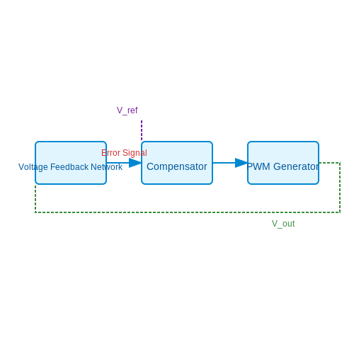
At the core of the voltage mode control strategy lies a closed-loop control system, which typically consists of the following key components:
- Voltage Feedback Network: This circuit samples the output voltage and feeds it back to the controller. The reference voltage is compared against the feedback voltage from the output, generating an error signal that represents the difference between these two voltages.
- Compensator: The error signal is processed by a compensator, which adjusts the duty cycle of the switch to bring the output voltage back to the desired level. The compensator's design is crucial for ensuring system stability and transient response.
- Pulse Width Modulation (PWM) Generator: The PWM circuit translates the output of the compensator into a duty cycle that effectively controls the switching element (typically a MOSFET) in the circuit.
Mathematical Foundation
The voltage control loop can be mathematically represented by the following equations:
Where:
- Vout: Output voltage.
- D: Duty cycle (ratio of on-time to total time of the switching period).
- Vin: Input voltage.
To analyze the stability of the system, we can introduce the Laplace transform to derive the transfer function. The control loop can be represented in the following standard form:
This construct allows you to evaluate the system's response to various dynamic inputs and determine the compensator's design to achieve a desired pole placement, essential for ensuring stability in real-world applications.
Applications and Practical Relevance
Voltage mode control is prevalent in applications requiring stable power supplies, such as in portable electronic devices, medical equipment, and renewable energy systems like solar inverters. Its simplicity makes it a favorable choice for many engineers; yet, in scenarios where load transients are critical, alternative approaches such as current mode control may be better suited.
To summarize, voltage mode control equips designers with a robust mechanism to achieve voltage regulation in DC-DC converters, ensuring that electronic devices operate reliably under a wide range of conditions. Further exploration of compensatory designs and stability criteria will enhance understanding and implementation clout in various engineering applications.
5.3 Current Mode Control
Current Mode Control (CMC) is an advanced control technique extensively applied in DC-DC converters to enhance performance metrics such as stability, transient response, and noise immunity. By regulating the converter’s output based on the inductor current rather than the voltage directly, CMC facilitates improved performance during load transient conditions. This approach allows for greater flexibility in design and is particularly effective in maintaining desired output parameters in response to changing input or load conditions.
Fundamental Principles of Current Mode Control
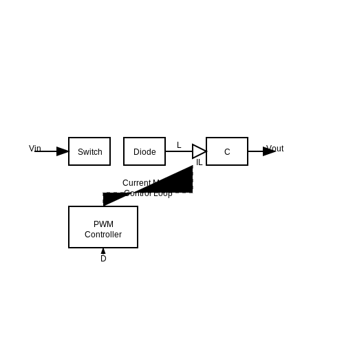
At its core, Current Mode Control operates by directly measuring the inductor current, which is used as a feedback signal to regulate the pulse width modulation (PWM) signal driving the switch. This contrasts with Voltage Mode Control (VMC), where the output voltage is the primary feedback variable. The significant advantage of CMC is its inherent ability to limit the current within the inductor, thus providing a natural method for overcurrent protection.
In terms of implementation, CMC requires the integration of a current sensing mechanism, often achieved through a low-value resistor in series with the inductor or a current transformer. This setup provides a real-time measurement of the inductor current, which can be compared against a reference. The resulting error signal is then used to modulate the duty cycle of the PWM signal.
Mathematical Modeling
To understand how Current Mode Control works mathematically, let's examine a basic buck converter model using this control scheme. The core equation governing the inductor current, \( I_L \), can be derived from the basic energy balance principle in inductive circuits:
Rearranging it gives us:
Under current mode control, we introduce a controlled PWM duty cycle, \( D \), which determines the time the switch is on:
This relationship indicates that the inductor current is directly influenced by the duty cycle of the PWM signal, creating a direct feedback where any increase in current manifests an increase in the PWM duty cycle to maintain stability.
Stability and Compensation
One of the main challenges in implementing CMC is ensuring system stability amidst variable operating conditions. Unlike VMC, where the system can exhibit oscillatory behavior under certain load transients, CMC provides a more stable dynamic response due to the inner current loop compensating for input voltage fluctuations. However, it is essential to design an appropriate compensation network to refine the frequency response of the system, prevent instability, and ensure robust performance.
Applications and Practical Considerations
Current Mode Control is widely utilized in various applications ranging from battery management systems to high-frequency switching power supplies. Its ability to limit peak current makes it particularly valuable in applications requiring tight safety margins, such as automotive power supplies and renewable energy systems.
Furthermore, the flexibility of CMC permits adaptation to various control modes, including peak current mode control (PCMC) and average current mode control (ACMC), further enhancing its utility in modern power electronics scenarios. Understanding the implications of different current control strategies allows engineers to tailor solutions that meet specific performance criteria while ensuring efficiency and reliability.
In summary, Current Mode Control offers a robust methodology in managing DC-DC converter operations, leveraging real-time current feedback for improved stability and performance. Therefore, understanding its principles and applications is crucial for engineers aiming to optimize power converter designs in today's fast-evolving technological landscape.
5.4 Digital Control Techniques
In the realm of DC-DC converters, the integration of digital control techniques represents a paradigm shift in the way power electronics systems are designed and operated. Traditional analog control methods have served well in various applications; however, the demand for enhanced performance metrics such as efficiency, transient response, and flexibility has elevated digital control to a critical role in modern converter design.
Digital control techniques leverage microcontrollers or digital signal processors (DSPs) to manage the operation of DC-DC converters, allowing for precise control over output voltage, current, and other conditions. This section explores the core principles of digital control while also delving into practical implementations and advantages.
Overview of Digital Control Techniques
The essence of digital control in DC-DC converters lies in its ability to process signals and execute control decisions with high precision and flexibility. Unlike analog controllers, which often suffer from limitations such as sensitivity to component tolerances and temperature variations, digital control systems can be programmed to adapt to varying operational conditions and performance requirements.
- Real-time processing: Digital controllers can handle fast computations and decision-making tasks, leading to improved dynamic performance.
- Programmability: The control algorithms can be easily modified, enabling rapid prototyping and implementation of various strategies.
- Enhanced diagnostics: Digital systems often incorporate advanced fault detection and condition monitoring, increasing reliability.
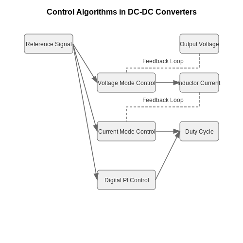
Control Algorithms
Several control algorithms can be applied in digital control of DC-DC converters. Among the most prevalent are:
- Voltage Mode Control: This method regulates the output voltage by comparing it to a reference signal and adjusting the duty cycle of the converter accordingly. Voltage mode control is straightforward but can struggle with stability under varying load conditions.
- Current Mode Control: By incorporating inductor current feedback, current mode control enhances response to load transients and improves system stability. The control loop consists of a voltage compensation in the outer loop and a current feedback in the inner loop.
- Digital Proportional-Integral (PI) Control: This classic control strategy combines proportional and integral actions to maintain desired output characteristics, allowing for steady-state error minimization.
Implementation Considerations
The transition from analog to digital control necessitates careful consideration of certain aspects to ensure effective performance:
- Sampling Rate: The performance of a digital controller is heavily influenced by the sampling rate. Selecting an adequate sampling frequency is crucial for accurately tracking changes in output voltage and load conditions.
- Quantization Effects: The binary representation of control signals can introduce quantization noise. Designers must account for this and implement algorithms that mitigate its impact.
- Latency: The inherent processing delay in digital systems requires thorough analysis to prevent instability, particularly in high-frequency applications.
Practical Applications
Digital control techniques have found extensive applications across various sectors:
- Renewable Energy Systems: Digital controllers are essential in managing the output from solar inverters and wind turbine converters, optimizing efficiency and performance under fluctuating input conditions.
- Electric Vehicle Chargers: Advanced digital control strategies improve charging processes by providing fast response times and enhancing power factor correction.
- Consumer Electronics: From laptops to smartphones, digital power management improves battery efficiency and extends device lifespan.
Overall, the adoption of digital control techniques in DC-DC converters not only augments their capabilities but also fosters innovation across various fields by enhancing performance, reliability, and usability.
6. Component Selection
6.1 Component Selection
When designing a DC-DC converter, the selection of components plays a critical role in ensuring the converter's efficiency, reliability, and overall performance. This selection process is nuanced, requiring a thorough understanding of various factors including electrical characteristics, thermal management, and application-specific requirements. In this section, we will delve into the essential components typically used in DC-DC converters, incorporating analysis and practical considerations.Understanding Key Components
Every DC-DC converter comprises key components such as switches, inductors, capacitors, diodes, and control circuits. The efficiency and performance of the converter heavily depend on the specifications of these elements.Switches
The choice of switching devices in a DC-DC converter—typically MOSFETs or IGBTs (Insulated Gate Bipolar Transistors)—is pivotal. One must consider the following attributes:- On-state Resistance (Ron): A lower Ron ensures reduced conduction losses.
- Gate Charge (Qg): This affects the switching speed and efficiency; a lower gate charge means faster switching.
- Maximum Voltage and Current Ratings: Ensure that the device can handle the peak voltage and current in the application.
Inductors
Inductors play a crucial role in energy storage and voltage conversion. Selecting the correct inductor involves evaluating factors such as:- Inductance Value: Sizing the inductor based on the converter topology is crucial for achieving desired ripple current.
- Saturation Current: Ensure it is above the peak current in the application to avoid inductor hard saturation, which can lead to overheating.
- Core Material: The material affects efficiency, leakage, and losses. Ferrite cores are common for high-frequency applications.
Capacitors
Capacitors are essential for filtering and energy smoothing in DC-DC converters. The selection should consider:- Capacitance and Voltage Rating: Higher capacitance values are typically needed for larger ripple current.
- Equivalent Series Resistance (ESR): Lower ESR values can minimize power losses during operation.
- Temperature Coefficient: Capacitors should operate effectively across the expected temperature range.
Diodes
In most converter topologies, diodes are integral in conducting current during specific phases of operation. Important considerations include:- Forward Voltage Drop (Vf): Opt for Schottky diodes for low Vf, which can reduce conduction losses.
- Reverse Recovery Speed: Fast recovery diodes prevent reverse current flow that could lead to switching losses.
Control Circuitry
Lastly, the control circuitry, which handles feedback and regulates the output voltage, shouldn't be overlooked. Essential elements include:- Control Method: Select the method (e.g., voltage-mode or current-mode control) that aligns with your design constraints.
- Loop Compensation: Ensure stability across variations in load and input conditions.
Real-World Applications
The careful selection and integration of components in DC-DC converters have significant implications in real-world scenarios. For example, in portable electronic devices, high efficiency in DC-DC converters maximizes battery life and performance. In renewable energy applications, such as solar inverters, high-frequency converters with optimized components can adapt to varying input conditions, ensuring maximum power point tracking. In summary, selecting the right components for DC-DC converters involves an intricate balance of performance parameters tailored to specific applications. This selection not only influences the operational efficacy but also the longevity and reliability of the overall system. As converter technology continues to evolve, engineers must remain vigilant in staying abreast of advancements in component technology to harness the full potential of DC-DC converters.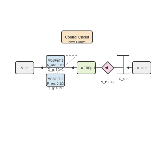
6.2 PCB Design Guidelines
When designing printed circuit boards (PCBs) for DC-DC converters, certain guidelines must be followed to optimize performance, reduce noise, and increase reliability. The complexity of power electronics circuits, combined with the critical nature of the components involved, necessitates a thorough understanding of PCB design principles in order to achieve an efficient and robust power management system.
Understanding Signal Integrity
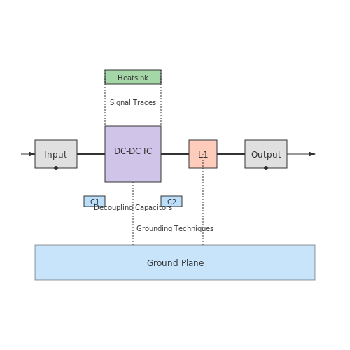
Signal integrity is paramount in high-frequency applications such as DC-DC converters. Consider the effect of parasitic inductance and capacitance in traces, which can distort signals and result in increased electromagnetic interference (EMI). To mitigate these issues:
- Keep traces short: Reducing trace length minimizes parasitic inductance and resistance.
- Utilize ground planes: A continuous ground plane helps to provide a low-inductance return path for the signals.
- Avoid sharp corners: Use arcs or 45-degree angles to reduce reflections and discontinuities.
Thermal Management
Efficient thermal management is crucial for the reliability of a DC-DC converter. As power levels increase, so does the heat generated by components. Poor thermal design can lead to overheating and component failure. To effectively manage heat:
- Use thermal vias: These allow heat to flow from the component side to the ground plane or heat sink.
- Incorporate heatsinks: Attach heatsinks to power components to enhance heat dissipation.
- Properly space components: Ensure adequate space between heat-generating components to allow for airflow.
Component Placement
The physical arrangement of components on the PCB can significantly affect performance. A well-thought-out layout enhances both electrical performance and manufacturability:
- Group related components: Place inductors, capacitors, and switches close to each other to minimize the loop area and reduce inductance.
- Follow a hierarchal layout: Arrange components from input to output to maintain signal flow and facilitate troubleshooting.
- Consider component height: Be cautious of varying heights of components, which can complicate assembly and increase manufacturing costs.
Grounding Techniques
Implementing a robust grounding strategy is essential in PCB design to prevent ground loops and minimize noise interference:
- Star grounding: Use a single ground point for all components to avoid ground potential differences.
- Use multiple ground planes: Different planes for analog and digital grounds can effectively reduce coupling issues.
- Encapsulate sensitive parts: Shield critical components and traces with grounded copper areas.
Decoupling Capacitors
Decoupling capacitors play a significant role in stabilizing the power supply and filtering out high-frequency noise. Positioning these capacitors is crucial:
- Place decoupling capacitors close to the IC pins: This configuration minimizes the inductance in the connection path.
- Use multiple capacitor values: Mix different capacitor sizes to cover a broad frequency range of noise.
Final Considerations
In summary, the design of PCBs for DC-DC converters requires careful consideration of factors such as signal integrity, thermal management, component placement, grounding techniques, and decoupling strategies. By adhering to these guidelines, designers can build more efficient and reliable power systems.
6.3 Thermal Management
Thermal management in DC-DC converters is a critical aspect that directly impacts performance, reliability, and lifespan. With the increasing demand for higher efficiency and miniaturization in electronic devices, managing heat dissipation effectively has become more crucial than ever.
DC-DC converters typically operate by switching transistors on and off, which inherently generates heat. The amount of heat produced depends on various factors including load current, switching frequency, and the efficiency of the converter topology. Understanding these factors and implementing efficient thermal management techniques is essential for ensuring optimal operation.
Importance of Thermal Management
Effective thermal management serves multiple purposes in DC-DC converters:
- Maintaining Performance: High temperatures can lead to performance degradation. For instance, in a buck converter, elevated temperatures can reduce operational efficiency.
- Enhancing Reliability: Prolonged exposure to excessive heat can significantly shorten the lifespan of electronic components, leading to premature failures.
- Ensuring Safety: Excessive heat accumulation can lead to dangerous situations, including potential fire hazards.
Heat Generation Mechanisms
To tackle thermal management efficiently, it is vital to understand how heat is generated within DC-DC converters. Key sources of heat include:
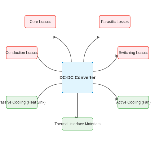
- Conduction Losses: These losses arise when current flows through resistive components such as inductors and transformers.
- Switching Losses: Each time a transistor switches on or off, energy is lost as heat. Switching losses are influenced by the switching frequency and the rise and fall times of the voltage and current waveforms.
- Core Losses: Magnetic components in the converter, like inductors and transformers, also generate heat due to hysteresis and eddy currents within their cores.
- Parasitic Losses: These include unexpected resistances due to PCB traces and other component layouts that can also contribute to overall heat generation.
Thermal Management Techniques
To mitigate the effects of heat generation, several thermal management techniques can be employed:
Passive Cooling
This includes using heat sinks and thermal pads to disperse heat effectively. Heat sinks absorb heat generated from the components and dissipate it into the surrounding air. The effectiveness of a heat sink can often be characterized by its thermal resistance, Rθ, which is expressed in degrees Celsius per watt (°C/W).
For example, the thermal resistance can be calculated using:
Where ΔT is the temperature rise above ambient and P is the power dissipated.
Active Cooling
In scenarios where passive cooling is inadequate, active cooling solutions such as fans or liquid cooling systems can be utilized. Active cooling systems increase heat transfer by forcing air or liquid circulation around components, significantly enhancing heat dissipation.
Thermal Interface Materials (TIMs)
Using high-performance thermal interface materials between components and heat sinks helps improve thermal conductivity and transfer efficiency. These materials fill in microscopic gaps, reducing thermal resistance.
Simulation and Modeling for Thermal Management
Modern design practices often employ thermal simulation tools to model the heat distribution and thermal behavior of DC-DC converters. Software platforms such as ANSYS and COMSOL Multiphysics allow engineers to create detailed models of thermal profiles, enabling them to predict how changes in design can impact thermal management.
Understanding thermal dynamics through simulation helps optimize layout and component selection, enhancing both efficiency and reliability.
Conclusion
In conclusion, the need for robust thermal management in DC-DC converters cannot be understated. As applications demand higher efficiency and compact designs, the strategies for managing heat must evolve accordingly. By employing a combination of passive and active cooling techniques, utilizing high-quality TIMs, and leveraging simulations, engineers can ensure their designs not only function effectively but also withstand the rigors of operational stresses.
6.4 Testing and Troubleshooting
In the realm of DC-DC converters, efficient testing and systematic troubleshooting are pivotal in ensuring the reliability of the circuit and optimal performance of the system. By deeply understanding the common issues and methodologies for analysis, engineers and researchers can maintain high standards in device functionality and lifespan.Understanding the Testing Process
Testing DC-DC converters involves a range of techniques aimed at assessing their performance characteristics, including voltage regulation, efficiency, load response, and transient behavior. Each parameter must be meticulously evaluated to guarantee that the converter performs within specified constraints. The following sections delve into critical testing methodologies.1. Basic Testing Parameters
When initiating testing, focus on these key parameters:- Input and Output Voltages: Measure the input voltage source to ensure that it is stable and within operational limits. Compare output voltage against expected values under different load conditions.
- Current Draw: Utilize a digital multimeter to gauge input and output currents, which aids in determining efficiency and identifying potential load issues.
- Temperature Rise: Utilize infrared thermometers or thermal cameras to monitor heat dissipation, testing for components exceeding temperature limits.
2. Advanced Testing Techniques
Beyond basic measurements, sophisticated techniques allow for nuanced assessments:Step Load Tests
Applying a step load change enables one to analyze dynamic response characteristics. Gradually increase and then decrease the load, observing how quickly and accurately the converter stabilizes at its output voltage. The Khan-Rush model, a standard approach to understanding transient response in DC-DC converters, can be used during this testing phase. This model characterizes the behavior of the output voltage in terms of overshoot, settling time, and ringing.Efficiency Measurement
Efficiency can be established with the formula:- Measure voltage and current at both the input and output terminals.
- Use resistive load banks or electronic loads for precise control over load conditions.
3. Troubleshooting Common Issues
Following testing, troubleshooting emerges as a critical process when deviations from expected performance arise. Typical issues include:- Output Voltage Ripple: High-frequency noise signals manifest as ripple in the output voltage, primarily influenced by input voltage variations and switching ripple current.
- Overheating Components: Excessive heat can arise from inadequate cooling, incorrect component values, or high-frequency losses. Systematically inspecting each component can identify faults leading to overheating.
- Instability under Load: If the system fails to maintain voltage under varying load conditions, scrutinize the feedback loop compensation and the stability margins set by control algorithms.
Implementing Feedback and Control Systems
Incorporating effective feedback and control mechanisms can significantly enhance converter reliability. Voltage feedback loops adjust the PWM signal in response to output voltage changes, maintaining tight regulation. This aspect becomes particularly relevant in modern applications requiring real-time adaptive responses to load changes. Developing a control strategy rooted in classical control theory, or employing advanced digital signal processors (DSP) for more sophisticated algorithms, can optimize performance under a range of conditions.Conclusion
The complex interplay of testing and troubleshooting DC-DC converters is vital for both initial designs and ongoing maintenance in applications ranging from consumer electronics to industrial systems. Mastering these processes not only ensures expected performance but can lead to innovations and improvements in power management technology, driving forth the future of electric and electronic devices. By utilizing systematic testing methodologies and adaptive troubleshooting techniques, engineers can minimize downtime and enhance the longevity of DC-DC converter designs, ultimately achieving greater reliability and efficiency in their projects.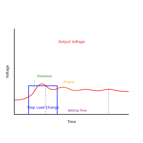
7. Renewable Energy Systems
7.1 Renewable Energy Systems
The integration of DC-DC converters into renewable energy systems is a critical topic in modern energy conversion technologies. As the demand for efficient energy management continues to rise, particularly with the global shift towards sustainability, understanding the role of these converters becomes essential.
DC-DC converters serve as vital components in renewable energy systems by enabling the efficient conversion of one DC voltage level to another. This capability is particularly important as renewable energy sources, such as solar and wind, often produce variable voltage outputs that need regulation for effective utilization and storage. For instance, solar panels may generate a voltage output that significantly fluctuates based on sunlight conditions. Thus, employing a DC-DC converter allows for optimal charging of batteries and ensures that the output voltage remains within the required range for subsequent devices or grid integration.
Types of DC-DC Converters in Renewable Energy Systems
In renewable energy systems, several types of DC-DC converters are commonly used, each with its distinct advantages:
- Buck Converters: These step down the input voltage to a lower output voltage. They are especially useful in battery-powered applications where energy efficiency is paramount.
- Buck-Boost Converters: Capable of stepping down and stepping up voltage levels, these converters are versatile and can cater to various energy source profiles.
- Boost Converters: Used primarily to step up voltage, boost converters are crucial in applications where the renewable source voltage must be elevated for charging or use.
The selection of a particular converter type hinges on the specific operational requirements of the renewable energy system and the nature of the energy source involved.
Efficiency and Performance
The performance of DC-DC converters in renewable systems is measured primarily by their efficiency, which indicates how effectively a converter can manage power without excessive loss during operation. The efficiency can be influenced by various factors:
- Switching Frequency: Higher frequencies can lead to smaller components but may introduce more losses due to switching.
- Input and Output Capacitors: The choice and quality of capacitors impact ripple and transient response, which are crucial for maintaining stable operation during fluctuations in renewable input.
- Control Techniques: Various control strategies (voltage mode, current mode, etc.) impact how optimally the converter responds to changes in load and input conditions.
Optimizing these parameters ensures that the DC-DC converter operates efficiently across a range of conditions, contributing to the overall performance of the renewable energy system.
Case Study: Solar Photovoltaic Systems
A practical example of the application of DC-DC converters can be found in solar photovoltaic (PV) systems. PV cells generate DC electricity, which can vary widely based on environmental conditions. Here, a maximum power point tracking (MPPT) algorithm is commonly integrated alongside a DC-DC converter to ensure that the system extracts the maximum available power from the solar panels, regardless of variations in voltage.
The MPPT algorithm adjusts the duty cycle of the buck or buck-boost converter based on real-time measurements of voltage and current from the solar array, dynamically optimizing power extraction. This results not only in higher energy yields but also in improved lifespan and reliability of the overall system through reduced operational stress.
Additionally, these renewable energy systems often involve grid interaction. When connected to a grid, maintaining synchronization becomes crucial, which presents additional challenges that may be addressed by incorporating advanced control schemes in the DC-DC converter’s design.
In conclusion, DC-DC converters are indispensable in modern renewable energy systems, enabling efficient energy conversion, regulation, and management. Their diverse applications, ranging from managing fluctuations in solar power output to facilitating grid interactions, highlight their critical role in advancing sustainable energy technologies.
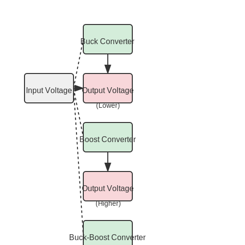
7.2 Electric Vehicles
In the rapidly evolving landscape of electric vehicles (EVs), DC-DC converters play a pivotal role in the management and conversion of electrical energy. Central to the functionality of electric vehicles, these converters enable efficient power distribution from the energy storage system to various vehicle components, ensuring optimal performance and longevity. DC-DC converters are designed to either step up (boost) or step down (buck) the input voltage from the battery packs to meet the different voltage requirements of onboard systems, such as the electric motor, charging units, and auxiliary electronics. The advent of modern electric vehicles has seen an increasing complexity in power systems, necessitating advanced DC-DC converter designs that optimize efficiency, weight, and cost-effectiveness.Importance of DC-DC Converters in Electric Vehicles
Electric vehicles rely heavily on high-capacity battery systems, often operating at a nominal voltage between 300V and 400V. However, not all components within the vehicle can operate at this high voltage level. Here’s where DC-DC converters come into play:- Voltage Regulation: They provide necessary voltage levels to various components, from control systems operating at low voltages (typically 12V or 24V) to drive systems needing higher voltages.
- Power Distribution: A well-designed power management system utilizing DC-DC converters can efficiently distribute power across multiple subsystems, enhancing overall vehicle operational efficiency.
- Regenerative Braking: DC-DC converters facilitate the process of converting mechanical energy back into electrical energy, which is then stored in the electric vehicle’s battery, improving overall energy utilization.
Types of DC-DC Converters in Electric Vehicles
The choice of DC-DC converter technology is critical, as each type of converter presents its advantages and challenges:Buck Converters
Buck converters are primarily used to step down voltage. They are known for their high efficiency, often exceeding 90%, and are commonly employed to power auxiliary circuits such as infotainment systems and lighting. The basic operation of a buck converter involves the switching of a transistor that connects the input voltage to an inductor and a load. The energy stored in the inductor is then transferred to the output during the switching cycles.Boost Converters
In contrast, boost converters enhance voltage levels, allowing for efficient power delivery to components requiring a higher input voltage than the battery provides. These are essential in scenarios where the battery voltage must be increased, for example, to drive an electric motor at a higher speed. The operation relies on storing energy in an inductor, and when the switch (transistor) opens, the energy is released to the output, thus stepping up the voltage.Bidirectional Converters
Bidirectional converters allow energy flow in both directions, proving particularly useful in vehicle-to-grid (V2G) applications, where energy can be fed back to the grid during peak demand periods. This technology supports smart energy management systems facilitating both charging and discharging of the battery, thereby enhancing the efficiency of energy use and ensuring battery health.Graphical Representation of a Buck Converter
A diagram of a typical buck converter would illustrate the essential components: the input source (battery), a control switch (transistor), a diode, an inductor, and an output capacitor. Each component's role in the energy conversion and storage process can be visually detailed to clarify the operational flow.Challenges and Advances
While DC-DC converters provide invaluable functionality, engineering challenges remain. High power densities and the thermal management of converters can impede system efficiency and reliability. Recent advances have integrated wide-bandgap semiconductors, such as silicon carbide (SiC) and gallium nitride (GaN), into converter designs. These materials allow for higher switching frequencies and reduced losses, further enhancing efficiency and compactness critical for electric vehicle applications. Furthermore, the industry is witnessing a trend towards increased modular designs, enabling easy scalability and integration into different vehicle architectures. The interplay of these innovations is shaping the future of electric vehicles, reflecting a move towards more sustainable and efficient personal and public transport systems. In conclusion, understanding the operational principles and systems involved in DC-DC converters is essential for advanced applications within electric vehicles. The ongoing research and technological developments promise to streamline existing challenges, paving the way for the next generation of efficient and reliable electric mobility solutions.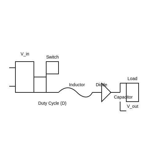
7.3 Consumer Electronics
DC-DC converters play a pivotal role in consumer electronics, where the demand for energy efficiency, compact device design, and variable output requirements are indispensable. In an era where electronic devices have become embedded in nearly every facet of daily life—from smartphones to laptops and wearables—the importance of optimizing power supply systems cannot be overstated.
To navigate through the intricacies of DC-DC conversion in consumer electronics, we need to consider two primary functions: voltage regulation and power conversion. Voltage translating ensures stable operations across varying input voltage conditions, whereas power conversion reduces or increases voltage levels to suit specific device needs.
Applications in Consumer Electronics
DC-DC converters find applications across a plethora of consumer electronics, serving as the backbone for devices that require strict voltage levels to operate efficiently. Below are some notable applications:
- Mobile Devices: Smartphones and tablets frequently utilize DC-DC converters to manage battery voltage and efficiently power demanding components, such as GPS and cameras.
- Laptops: In laptops, these converters help in optimizing battery life and thermal management by ensuring that different components operate within their nominal voltage ranges.
- Wearable Technologies: Compact and low-power DC-DC converters enable wearables to function effectively while conserving battery life, maintaining minimal physical footprint.
- LED Lighting: LED lamps require a constant current drive to ensure consistent brightness, for which DC-DC converters are specifically designed to provide.
Types of DC-DC Converters
There are primarily three types of DC-DC converters utilized within consumer electronics:
- Buck Converters: These step down the input voltage while increasing the output current, making them ideal for mobile phones, which require lower voltages.
- Boost Converters: These increase the input voltage while decreasing the output current, suitable for applications where higher voltages are necessary, such as LED drivers in displays.
- Buck-Boost Converters: Combining the features of both buck and boost converters, they allow voltage to be stepped up or stepped down, catering to variable load requirements in smart devices.
Efficiency Considerations
A critical aspect of deploying DC-DC converters in consumer electronics is efficiency. The efficiency of a DC-DC converter is defined as the ratio of output power to input power, expressed mathematically as:
This efficiency directly influences battery life in portable devices. High-efficiency converters reduce power loss, limit heat generation, and improve the overall sustainability of electronic products. In designing converters for consumer electronics, engineers often employ synchronous rectification, which minimizes voltage drop in the switching components, thus enhancing performance.
Future Trends
The future of DC-DC converters in consumer electronics looks promising, with advancements in materials science, particularly the use of wide-bandgap semiconductors like silicon carbide (SiC) and gallium nitride (GaN). These materials allow for more efficient conversion processes and smaller form factors, crucial for the compact nature of modern gadgets.
As consumers demand more from their electronic devices, the development and integration of advanced DC-DC techniques will continue to evolve, aligning with trends like renewable energy integration, smart grid technology, and higher power density applications.
7.4 Industrial Applications
The implementation of DC-DC converters has transformed industrial applications, enhancing efficiency, performance, and reliability. Their ability to efficiently convert voltage levels while maintaining power levels makes them integral components across various sectors. We will explore several critical industrial applications of DC-DC converters, examining their roles in renewable energy systems, electric vehicles, telecommunications, and other areas.Power Supply for Renewable Energy Systems
In the realm of renewable energy, DC-DC converters are pivotal in managing power output from sources such as solar panels and wind turbines. These devices adjust the voltage to optimal levels, ensuring efficient energy harvesting and maximizing the usable power. In a solar panel system, for example, the output voltage may vary due to changing sunlight conditions. Here, a boost converter can elevate the voltage to match the requirements of the inverter that transforms DC to AC for grid distribution. Moreover, maximum power point tracking (MPPT) controllers utilize advanced DC-DC converters to optimize the energy extracted from solar panels. This process increases overall system efficiency significantly.Electric Vehicles
The use of DC-DC converters in electric vehicles (EVs) has become increasingly prevalent. These converters play a crucial role in managing the energy distribution from the high-voltage battery packs to various onboard systems, which often require different voltage levels. For instance, a typical EV may incorporate a buck converter to reduce the battery's high voltage (e.g., 400V) to a lower voltage (around 12V) needed for lighting, infotainment systems, and auxiliary devices. Similarly, boost converters may be utilized to step up voltage levels for electric motors during acceleration phases, ensuring efficient operation and extending the vehicle's driving range.Telecommunications
In telecommunications, DC-DC converters are essential components for powering telecommunication equipment. Base stations, routers, and other critical infrastructure often require specific voltage levels for optimal performance. Typically, distributed power architectures use DC-DC converters to facilitate localized voltage adjustments. These converters not only improve energy efficiency but also reduce the overall space and weight of the power conversion components. By utilizing techniques such as synchronous rectification and integrated circuit designs, modern converters are capable of providing high power density and efficiency, which is critical in the telecommunication sector.Industrial Automation and Robotics
Industrial automation applications leverage DC-DC converters to manage power needs in robotic systems and control equipment. In environments like manufacturing plants, precision in power delivery is vital for reliable operation. DC-DC converters allow for the modular design of systems, enabling different voltage supply levels for sensors, controllers, and actuators. Moreover, in robotics, where battery life and performance are critical, these converters help optimize energy usage, thereby extending operational time without sacrificing functionality.Conclusion
Ultimately, the versatility and efficiency of DC-DC converters make them indispensable in a range of industrial applications. As technology evolves, their integration will only deepen, pushing the limits of energy management in innovative ways, from renewable energy systems to automation and telecommunications. Understanding their role not only sheds light on current applications but also opens doors to future advancement in energy-efficient technologies.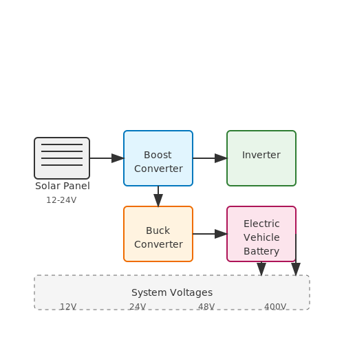
8. Advancements in Materials
8.1 Advancements in Materials
As technology pushes the boundaries of efficiency and performance in electronic systems, the advancement of materials plays a critical role, particularly in the development of DC-DC converters. These converters, crucial for efficient power management, benefit significantly from innovations that enhance their thermal performance, efficiency, and overall reliability.Understanding the Role of Materials
DC-DC converters rely on a range of materials to function effectively, primarily in their inductors, capacitors, and semiconductor devices. The choice of materials directly impacts the converter's efficiency, size, and thermal management capabilities. Consequently, advancements in materials science have become pivotal in addressing modern demands for higher power densities and lower energy losses.Semi-Conductive Materials
At the core of advancements in DC-DC converters is the evolution of semiconductor materials. Silicon has been the traditional workhorse, but its limitations in terms of thermal conductivity and efficiency at high frequencies have pushed researchers to explore alternatives. Notably, gallium nitride (GaN) and silicon carbide (SiC) have emerged as revolutionary materials:- Gallium Nitride (GaN): GaN enables higher switching frequencies, which results in smaller passive components. Its wide bandgap allows operation at higher voltages and temperatures, improving the thermal performance significantly.
- Silicon Carbide (SiC): SiC provides superior thermal conductivity and high breakdown voltage. This characteristic makes it ideal for high-power applications, offering higher efficiency and reducing the size of heat sinks.
Magnetic Materials in Inductors
The performance of inductors in DC-DC converters is also heavily influenced by the magnetic materials used in their construction. Traditionally, ferrite materials were favored due to their favorable magnetic properties at high frequencies. However, recent advancements have led to the development of nanocrystalline and amorphous magnetic materials, which further enhance performance:- Nanocrystalline Materials: These materials exhibit high permeability and low core losses, making them ideal for high-frequency applications. This leads to more efficient energy conversion in compact designs.
- Amorphous Alloys: Amorphous magnetic materials can reduce losses in inductors significantly, offering better efficiency at both low and high frequencies.
Dielectric Materials in Capacitors
Capacitors in DC-DC converters have also seen material advancements, especially in dielectrics. Conventional film capacitors, while reliable, tend to be bulky. Research into high-k dielectric materials, such as barium titanate (BaTiO3), enables smaller capacitor designs with improved energy density:- High-K Dielectrics: These new materials can significantly reduce the required capacitance volume while maintaining high voltage ratings, translating into smaller and lighter capacitors.
- Solid Electrolyte Capacitors: Innovations in solid electrolytes are paving the way for improved reliability and performance in capacitor technology, essential for power electronics in dynamic environments.
The Path Forward
As DC-DC converters become critical components in modern electronics, ongoing research in advanced materials promises to significantly enhance their efficiency, reliability, and miniaturization. The incorporation of novel semiconductor, magnetic, and dielectric materials is paving the way for the next generation of power management systems. Overall, keeping abreast of advancements in materials science is essential for engineers and researchers focusing on improving DC-DC converter technologies. By harnessing these innovations, it is possible to achieve not only higher efficiencies but also to meet the accelerating demands for compactness and reliability across various applications.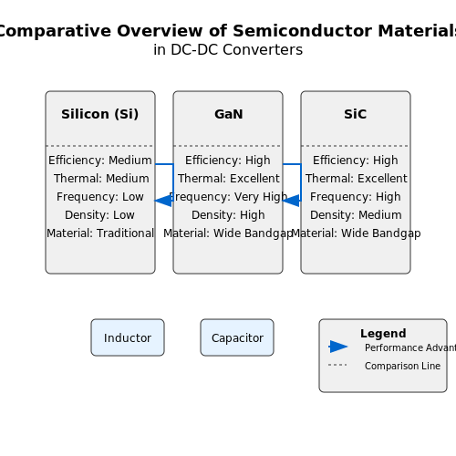
8.2 Integration with Digital Systems
The integration of DC-DC converters with digital systems has garnered attention due to the indispensable role they play in modern electronics. As devices become increasingly sophisticated and compact, the effective management of power supplies, which convert one DC voltage to another, becomes a critical component in maintaining performance and efficiency. This section discusses the principles governing the integration of DC-DC converters with digital systems, emphasizing practical applications, design considerations, and advancing technologies.
Understanding Digital System Requirements
Digital systems, such as microcontrollers, FPGAs, and various embedded systems, have specific power requirements that need to be met for optimal performance. These systems typically require a stable voltage supply, low ripple, and fast transient response. Given the rapid changes in load conditions in digital circuits, especially during high-frequency switching, DC-DC converters must be adept at providing a stable output voltage under varying load conditions.
This need for stability is compounded by the introduction of multilevel converters, which provide additional granularity in voltage control and efficiency. Such converters manage output voltage through multiple switches and control states, thus offering a more adaptable power supply solution.
Control Techniques for Enhancing Performance
Various control techniques can be utilized to enhance the performance of DC-DC converters when integrated with digital systems. These include:
- Pulse-Width Modulation (PWM): PWM is a popular technique where the width of the pulse is varied to control the output voltage. This method maximizes efficiency and minimizes ripple by efficiently switching the converter.
- Voltage Mode Control: This technique regulates output voltage by adjusting the duty cycle based on feedback from the output. It is simple yet effective for stable voltage regulation.
- Current Mode Control: By sensing output current and regulating it, current mode control improves transient response and provides inherent overcurrent protection, making it suitable for varying load conditions.
Case Study: Power Management in Embedded Systems
To illustrate the significance of these integrations, consider a case study involving power management units (PMUs) used in portable devices, such as smartphones. These systems utilize multiple DC-DC converters to efficiently power various components, including processors, displays, and sensors, each with different voltage requirements.
The integration of these converters must account for priorities dictated by power saving modes, sleep modes, and dynamic voltage scaling. For instance, when a smartphone transitions from active to sleep mode, the PMU must rapidly adjust output voltages to minimize power consumption while ensuring that critical systems remain functional.
Future Prospects and Challenges
As technology advances, the integration of DC-DC converters with digital systems is expected to evolve significantly. Emerging fields such as Internet of Things (IoT) devices and wearables will require even more sophisticated power management solutions, demanding increased efficiency and reduced size. Furthermore, the advent of digital control algorithms, including machine learning techniques, may facilitate smarter and more adaptive DC-DC converters capable of real-time adjustments based on system requirements.
However, this integration also poses challenges, such as electromagnetic interference (EMI) and thermal considerations, which require advanced design techniques to minimize their impact on system reliability and performance.
In summary, the synergy between DC-DC converters and digital systems is crucial for optimizing power performance in contemporary applications. With ongoing innovations in control strategies and component design, the future holds tremendous potential for enhancing the efficiency and functionality of electronic devices.
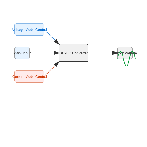
8.3 Miniaturization and Efficiency Improvements
In the realm of power electronics, the pursuit of miniaturization and enhanced efficiency in DC-DC converters represents a convergence of cutting-edge technology and deep engineering innovation. As applications continue to demand smaller form factors, such improvements directly impact everything from consumer electronics to electric vehicles. Achieving this balance requires an understanding of the underlying principles as well as the integration of advanced technologies.
The primary measure of efficiency in DC-DC converters can be expressed by the ratio of the output power to the input power:
where \( P_{out} \) represents the power delivered to the load, and \( P_{in} \) indicates the total power consumed from the source. As converter designs scale down in size, addressing losses becomes crucial for maintaining the energy efficiency that is often specified in performance metrics.
Key Areas for Improvement
The miniaturization of DC-DC converters can be achieved through several approaches, focusing primarily on power density, integration, and materials:
- Reduced Component Size: Advances in component fabrication technologies have allowed for the production of smaller, higher-frequency inductance and capacitance elements that significantly reduce overall converter footprint.
- Integrated Solutions: Utilizing integrated circuits for control and converter functions minimizes the number of separate components required, which not only saves space but also improves reliability and thermal management.
- New Materials: The advent of high-permittivity dielectrics and improved ferromagnetic materials allows for smaller passive components without compromising performance. Additionally, wide-bandgap semiconductors (like SiC and GaN) enable higher switching frequencies, reducing required passive component sizes.
Challenges of Miniaturization
While the benefits are significant, various challenges accompany the move toward miniaturization:
- Thermal Management: As components become more densely packed, dissipating heat becomes critical. Innovative heat dissipating techniques, such as micro-channel cooling or advanced thermal interface materials, are being explored to mitigate thermal effects.
- Noise and Electromagnetic Interference (EMI): Smaller components can lead to an increase in electromagnetic interference, necessitating sophisticated shielding techniques and careful layout designs to maintain performance.
Efficiency Improvements through Advanced Topologies
In terms of circuit design, the choice of converter topology can dramatically impact both efficiency and miniaturization. Among popular types, buck, boost, and buck-boost converters each have unique traits conducive to different applications, but novel topologies such as synchronous converters have emerged as leading designs.
Synchronous converters use controlled switches rather than diodes to reduce conduction losses, further enhancing efficiency. An example of current control in synchronous buck converters can be mathematically derived by analyzing the time-averaged output voltage in relation to the duty cycle:
Here, D represents the duty cycle, defined as the ratio of the time the switch is 'on' to the total switching period, aiding in achieving higher efficiency during operation.
Real-World Applications
Miniaturized and efficient DC-DC converters find critical roles across many industries:
- Consumer Electronics: Laptops and smartphones feature highly compact power management systems that need to manage diverse power requirements efficiently.
- Electric Vehicles: High-performance battery management systems require compact, efficient converters to maximize range and minimize weight.
- Industrial Applications: Automation systems often employ miniaturized DC-DC converters for sensors and communication devices, making system integration far easier.
In closing, the ongoing advancement of technology in miniaturization and efficiency improvements within DC-DC converters promises a future where electronic devices are not only powerful but also exceedingly compact, aligning with the growing demands of our increasingly connected world.
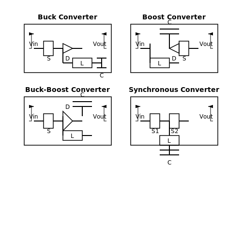
9. Recommended Textbooks
9.1 Recommended Textbooks
- DC-DC Converters: Design and Optimization — This textbook offers a comprehensive guide to DC-DC converter design, exploring both traditional and modern techniques with a focus on optimization for efficiency and performance.
- Fundamentals of Power Electronics — A detailed resource covering both the theoretical aspects and practical applications of power electronics, with a strong emphasis on DC-DC converters, circuit design, and control strategies.
- Switched-Capacitor Techniques for DC-DC Converters — This book delves into the specialized field of switched-capacitor technology, discussing its application in DC-DC converter circuits with detailed examples.
- Advanced DC-DC Converters — Provides in-depth coverage of advanced topics in DC-DC converter technology, including innovative topology designs and the latest developments in controlling and optimizing performance.
- Power Electronics: Devices, Circuits, and Applications — Widely utilized in academia, this book offers a blend of theory and practice, with sections dedicated to understanding DC-DC converter operations within larger power electronics systems.
- Power Electronics Handbook — A highly regarded handbook that includes detailed chapters on the theory and practical applications of DC-DC converters, offering valuable insights for both novice and experienced engineers.
- Modeling and Control of Power Converters — This resource delves into the mathematical modeling and control mechanisms of power converters, with a strong focus on enhancing the performance of DC-DC systems.
9.2 Research Papers on DC-DC Converters
- Performance of DC-DC Converter Topologies — This paper evaluates various DC-DC converter topologies, providing an in-depth analysis of their performance characteristics under different operating conditions.
- Overview of Continuous and Noncontinuous Modes in DC-DC Converters — A comprehensive study detailing the operation of DC-DC converters in both continuous and noncontinuous modes, focusing on the impact these modes have on efficiency and performance.
- Control Strategy for DC-DC Converters — This research paper presents various control strategies for DC-DC converters, emphasizing their stability and reliability in different applications.
- Energy Efficiency Optimization of DC-DC Converters — Focuses on methods to optimize energy efficiency in DC-DC converters, discussing technological advancements and practical implementations.
- Innovative Design Approaches for DC-DC Converters — Highlights innovative design methodologies for DC-DC converters, introducing novel topologies aimed at improving their performance.
- Analysis and Simulation of DC-DC Converter Dynamics — Presents a detailed analysis and simulation study of the dynamic behavior of DC-DC converters, providing insights into transient response optimization.
- Reliability Assessment of DC-DC Converters in Renewable Energy Systems — Discusses the reliability and robustness of DC-DC converters within renewable energy systems, focusing on lifecycle analysis and failure modes.
- Advanced Control Techniques for DC-DC Converters — Explores advanced control techniques used in modern DC-DC converters, highlighting their impact on efficiency and stability in complex power systems.
9.3 Online Resources
- Understanding Buck-Boost Power Stages in Switched Mode Power Supplies — An excellent resource by Texas Instruments providing a comprehensive guide on the principles and design considerations for buck-boost converters used in power supplies.
- Why use a Delta-Sigma ADC in a Switching Power Application — An insightful article that discusses the advantages of using delta-sigma ADCs in switching power applications to improve performance and efficiency.
- Modeling and Simulation of DC-DC Converters — A research paper available on ResearchGate that provides detailed modeling and simulation techniques for various DC-DC converters.
- DC-DC Converter Tutorial — A technical tutorial from Maxim Integrated that covers different types of DC-DC converters, their applications, and key design considerations.
- DC-DC Boost Converter Topologies - Part 1: Basics — The first part of a series on EETimes explaining the fundamental concepts and functionalities of boost converter topologies.
- 7 Things to Calculate When Designing Boost Converters — This article on EDN Network guides through essential calculations involved in designing efficient and robust boost converters.
- Review of DC-DC Converter Topologies Based on Smart Building — A review article in ScienceDirect discussing various DC-DC converter topologies used in smart building applications with a focus on their operational characteristics.
9.4 Industry Standards
In the world of DC-DC converters, industry standards play a critical role in ensuring compatibility, performance, and safety. These standards, developed by various international and regional organizations, provide guidelines on manufacturing, testing, and application of DC-DC converters. Understanding these standards is essential for engineers, manufacturers, and researchers working in this field.
Regulatory Bodies and Standard Organizations
Several regulatory bodies and organizations contribute to developing standards for DC-DC converters. Some of the most influential include:
- IEC (International Electrotechnical Commission): This organization develops international standards for a wide range of electronic devices, including DC-DC converters. Their standards ensure interoperability and safety.
- IEEE (Institute of Electrical and Electronics Engineers): IEEE focuses on advancing technology and provides standards that often bridge gaps in technology practices and operations for DC-DC converters.
- EN (European Norms): These standards are critical for products sold within the European Union, ensuring safety, and environmental protection.
- UL (Underwriters Laboratories): This North American safety consulting and certification company tests DC-DC converters for safe usage.
Key Standards for DC-DC Converters
Several standards are particularly pertinent to DC-DC converters, impacting their design, efficiency, and safety:
- IEC 62109: This standard outlines safety guidelines specifically for power converters employed in photovoltaic systems. It covers various aspects including insulation coordination, thermal management, and fault protection.
- IEC 60950: It sets out the safety requirements for equipment using low-voltage power supplies, targeting IT and business equipment, which often utilize DC-DC converters.
- IEEE 519: Focused on harmonic control in electrical power systems, this standard ensures converters do not introduce excessive harmonic distortion, maintaining system integrity and performance.
- EN 55022: This standard addresses the electromagnetic compatibility of equipment. DC-DC converters are evaluated for their emissions to avoid interference with other devices.
Impact on Design and Application
Adherence to these standards affects both the design and application of DC-DC converters. For designers, compliance ensures the product meets international safety and performance criteria, facilitating global market access. It also challenges designers to innovate within standard constraints, often leading to improved performance and efficiency.
For end-users, standardized converters bring assurance of reliability, safety, and interoperability with other systems. Additionally, products built to these standards are often more sustainable, incorporating energy-saving mechanisms and reducing waste.
Real-World Applications
Practically, industry standards have paved the way for a broad range of applications. Automotive, renewable energy, and telecommunication sectors heavily rely on standardized DC-DC converters. For example, electric vehicles use high efficiency converters to manage power between the battery and motor effectively, complying with automotive standards to ensure safety and performance.
In the renewable energy domain, standardized converters enable solar panels to connect to the grid or storage systems with minimal losses and maximal reliability, aligning with environmental and energy policies.