Electronics for Aerospace
1. Basic Electrical Concepts and Units
Basic Electrical Concepts and Units
Electricity forms the foundation of modern aerospace systems. To understand electronics in aerospace applications, it is crucial to grasp the fundamental electrical concepts and units that govern the behavior of circuits. Let's delve into these key principles.Electric Charge and Current
Electric charge is a fundamental property of matter. It is quantized, meaning it exists in discrete amounts. The charge on a single electron is approximately $$1.602 \times 10^{-19}$$ coulombs. Current ($$I$$) is defined as the rate of flow of charge and is measured in amperes (A).Voltage and Ohm's Law
Voltage ($$V$$) represents the energy per unit charge provided by a source in an electrical circuit. It is measured in volts (V). Ohm's Law relates voltage, current, and resistance:Resistance and Conductance
Resistance ($$R$$) is a measure of how much a material opposes the flow of electric current. It is given by:Power and Energy
Power ($$P$$) is the rate at which work is done in an electric circuit and is given by: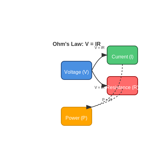
1.2 Circuit Theory and Analysis
In the realm of electronics for aerospace applications, a profound understanding of circuit theory and analysis is indispensable. This knowledge is foundational to designing, analyzing, and troubleshooting complex electronic systems that are integral to aerospace technology.
Basic Concepts
At its core, circuit theory deals with understanding how electrical circuits operate and how current and voltage interact within them. Key concepts include:
- Ohm's Law: Describes the relationship between voltage, current, and resistance in a circuit (V = IR).
- Kirchhoff's Laws: Summarize the concepts of conservation of charge and energy in electrical circuits.
- Network Analysis: Techniques such as nodal and mesh analysis are used to analyze complex circuits.
Analysis Methods
Various methods are employed to analyze circuits, depending on the complexity and requirements of the system:
- Nodal Analysis: Involves creating equations at circuit nodes to determine node voltages.
- Mesh Analysis: Involves applying Kirchhoff's voltage law to loop currents in the circuit.
- Thevenin and Norton Theorems: Simplify complex circuits into equivalent circuits for easier analysis.
Real-World Applications
The principles of circuit theory and analysis find widespread application in aerospace technology:
- Designing power distribution systems for spacecraft.
- Ensuring signal integrity in communication systems onboard satellites.
- Implementing fault detection and isolation mechanisms in avionics systems.
Understanding circuit theory and analysis is crucial for aerospace engineers to ensure reliable and efficient electronic systems in the demanding environment of space exploration.
1.3 Components Used in Aerospace Electronics
In the realm of aerospace electronics, the components utilized are crucial for the successful operation of various systems onboard spacecraft, satellites, and aircraft. These components are designed to withstand the harsh environments of outer space or high altitudes and must meet stringent reliability and performance requirements. ### Semiconductor Devices Semiconductor devices play a fundamental role in aerospace electronics due to their compact size, low power consumption, and high reliability. Components such as field-effect transistors (FETs), bipolar junction transistors (BJTs), and diodes are extensively used in signal processing, power distribution, and voltage regulation within aerospace systems. These devices are critical for controlling currents and voltages in different circuit configurations. ### Integrated Circuits Integrated circuits (ICs) are at the heart of modern aerospace electronics, consolidating multiple electronic components onto a single chip. The aerospace industry heavily relies on Application-Specific Integrated Circuits (ASICs), digital signal processors (DSPs), and microcontrollers for signal processing, data handling, and control functions. ICs are chosen for their high levels of integration, reliability, and customizability to meet specific mission requirements. ### Passive Components Passive components such as resistors, capacitors, and inductors are essential for designing aerospace circuits. Resistors are used to limit current flow, control voltages, and set bias points in various electronic systems. Capacitors are crucial for filtering noise, smoothing power supplies, and storing energy. Inductors are vital for creating magnetic fields, filtering signals, and regulating currents. These components are selected based on performance criteria and environmental constraints. ### Optoelectronic Devices Optoelectronic devices play a significant role in aerospace applications, enabling communication, navigation, sensing, and imaging functionalities. Light-emitting diodes (LEDs), photodiodes, and optocouplers are used in avionics, spacecraft controls, and optical communication systems. Optoelectronic devices offer advantages such as high-speed data transmission, electromagnetic interference immunity, and compact form factors, making them ideal for aerospace environments. ### RF and Microwave Components Radio frequency (RF) and microwave components are indispensable for wireless communication, radar systems, and satellite links in aerospace electronics. RF amplifiers, filters, mixers, and antennas are critical for signal reception, transmission, and processing. These components must meet stringent performance specifications in terms of bandwidth, gain, noise figure, and efficiency to ensure reliable communication and data transfer in aerospace missions. ### Thermal Management Components Thermal management is a critical aspect of aerospace electronics to ensure proper operation and longevity of electronic systems in extreme temperature conditions. Components such as heat sinks, thermal interface materials (TIMs), and temperature sensors are employed to dissipate heat, improve thermal conduction, and monitor temperature variations within electronic assemblies. Effective thermal management is essential for preventing overheating and maintaining optimal performance in aerospace applications. ### Navigation and Positioning Components Navigation and positioning components are essential for spacecraft guidance, orientation control, and satellite positioning in aerospace missions. Inertial measurement units (IMUs), GPS modules, and gyroscopes are used to determine the position, velocity, and orientation of aerospace vehicles relative to Earth or celestial bodies. These components enable precise navigation, attitude control, and trajectory tracking, facilitating mission success and operational efficiency in space exploration and satellite missions.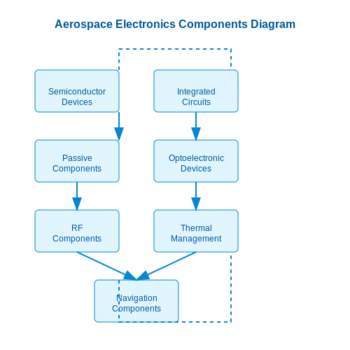
2. Avionics and Flight Control Systems
Avionics and Flight Control Systems
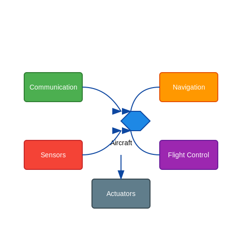
Avionics and flight control systems are critical components in modern aerospace engineering. These systems encompass a range of electronics and control mechanisms that are responsible for ensuring the safe and efficient operation of aircraft. Let's explore the key concepts and technologies involved in these systems. ### Introduction to Avionics Avionics refer to the electronic systems used in aircraft for communication, navigation, monitoring, and control. These systems play a vital role in enhancing the safety, efficiency, and performance of aircraft. #### Key Components of Avionics Avionic systems typically include: - Flight management systems - Navigation systems (GPS, inertial navigation) - Communication systems (radio, transponders) - Flight control systems (autopilot, fly-by-wire) ### Flight Control Systems Flight control systems regulate the orientation, speed, and trajectory of an aircraft. These systems integrate sensors, actuators, and control algorithms to maintain stability and control during flight. #### Types of Flight Control Systems 1. Mechanical Control Systems: Traditional systems using mechanical linkages to control surfaces like ailerons and elevators. 2. Hydraulic Control Systems: Utilize hydraulic actuators to move control surfaces, offering more precise control capabilities. 3. Fly-by-Wire Systems: Replace mechanical linkages with electronic systems for control, offering enhanced safety and automation features. #### Fly-by-Wire Systems Fly-by-wire systems are a crucial advancement in flight control technology. These systems use electronic interfaces to interpret pilot commands and autonomously adjust control surfaces, increasing efficiency and safety. ### Advancements in Avionics Modern avionics systems leverage cutting-edge technologies such as: - Integrated modular avionics - Glass cockpit displays - Advanced data communication protocols - Redundant systems for fault tolerance ### Practical Applications Avionics and flight control systems are essential in various aerospace applications, including: - Commercial aviation - Military aircraft - Unmanned aerial vehicles (drones) - Spacecraft guidance systems Understanding avionics and flight control systems is crucial for aerospace engineers and researchers working to enhance the safety and efficiency of aircraft operations.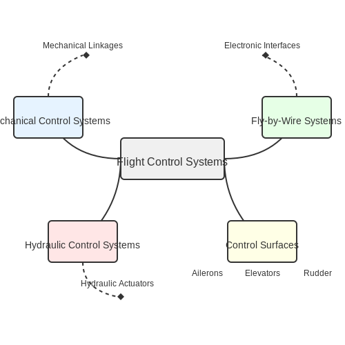
Navigation and Guidance Systems
Navigation and guidance systems play a critical role in aerospace applications, ensuring the accurate maneuvering and control of aerospace vehicles. These systems integrate various sensors, algorithms, and control mechanisms to enable precise navigation, trajectory planning, and target tracking. Let's delve into the key components and principles underlying navigation and guidance systems in aerospace engineering.
Sensor Fusion in Navigation
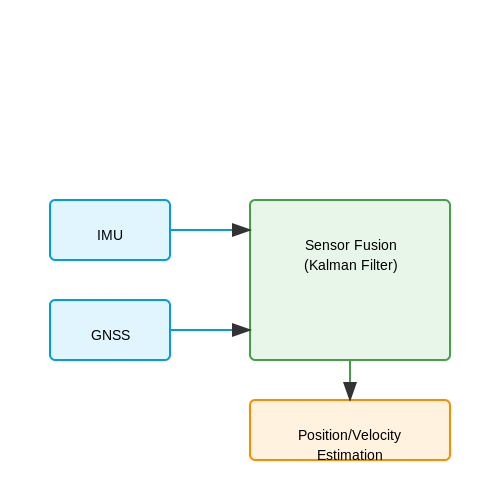
In aerospace, sensor fusion is vital for combining data from multiple sensors to enhance accuracy and reliability in navigation. By integrating inputs from inertial measurement units (IMUs), Global Navigation Satellite Systems (GNSS), and other sensors, aerospace systems can achieve robust position estimation, attitude determination, and velocity tracking. Sensor fusion algorithms, such as Kalman filters, play a crucial role in processing sensor data and minimizing errors.
Guidance Algorithms
Guidance algorithms in aerospace navigation dictate the trajectory planning and control decisions for vehicles. These algorithms utilize input from sensors, mission objectives, and environmental conditions to calculate optimal paths, perform mid-course corrections, and facilitate precision landing. From simple proportional navigation to advanced model predictive control, guidance algorithms ensure effective guidance and control of aerospace vehicles.
Autopilot Systems
Autopilot systems represent the brains of aerospace vehicles, executing guidance commands and stabilizing the vehicle during flight. These systems incorporate sophisticated control algorithms, such as PID controllers and adaptive control, to maintain stability, adjust attitude, and follow desired trajectories. Autopilot systems are essential for autonomous operation, enabling unmanned aerial vehicles (UAVs) and spacecraft to navigate complex environments with precision.
Real-Time Trajectory Optimization
Real-time trajectory optimization involves continuously adjusting the flight path of aerospace vehicles based on evolving conditions and constraints. By optimizing trajectories in response to changing dynamics, weather patterns, or mission priorities, aerospace systems can enhance efficiency, safety, and mission success. Dynamic programming, optimal control theory, and artificial intelligence techniques are employed for real-time trajectory optimization in aerospace applications.
Integration with Navigation Satellites
Navigation satellites, such as the Global Positioning System (GPS), play a significant role in aerospace navigation by providing reliable positioning and timing information. Aerospace systems integrate with navigation satellites to enhance position accuracy, enable precise timing synchronization, and support seamless navigation across global scales. Differential GPS, carrier phase tracking, and multi-constellation navigation are key techniques for robust satellite-based navigation in aerospace.
Case Study: Apollo Guidance Computer
The Apollo Guidance Computer (AGC) represented a groundbreaking advancement in aerospace navigation and guidance during the Apollo missions to the Moon. Developed by NASA and MIT, the AGC featured innovative integrated circuits and software tailored for space missions, enabling precise navigation, lunar landing, and rendezvous maneuvers. The AGC's role in the Apollo program showcases the importance of advanced guidance systems in achieving ambitious space exploration goals.
---
2.3 Communication Systems in Aircraft
Communication systems in aircraft play a critical role in ensuring seamless data transmission, navigation, and connectivity within and beyond the aircraft. These systems enable pilots, crew members, and ground control to exchange vital information in real-time, enhancing flight safety and efficiency.
Types of Communication Systems
There are several types of communication systems employed in aircraft:
- VHF (Very High Frequency) Communication: VHF systems are commonly used for short-range air-to-ground and air-to-air voice communication.
- HF (High Frequency) Communication: HF systems allow long-range communication, especially in remote areas or over oceans where VHF coverage is limited.
- Satellite Communication: Satellite communication systems provide global coverage, enabling constant connectivity even on transoceanic flights.
- ACARS (Aircraft Communications Addressing and Reporting System): ACARS facilitates text-based communication for messaging, weather updates, and maintenance data.
Key Components in Communication Systems
Communication systems in aircraft consist of various components:
- Transmitters and Receivers: These devices transmit and receive signals for voice and data communication.
- Antennas: Antennas are crucial for transmitting and receiving signals efficiently across different frequencies.
- Modems: Modems encode and decode data for transmission over communication channels.
- Control Panels: These interface components allow pilots to control and monitor the communication system.
Signal Processing in Communication Systems
Signal processing plays a key role in ensuring clear and reliable communication within aircraft systems. By employing techniques such as modulation, encoding, and error correction, communication systems mitigate interference and ensure accurate data transmission.
Real-Time Data Transmission
In modern aircraft, communication systems also support real-time data transmission for critical operations such as weather monitoring, flight tracking, and automated reporting. These systems integrate with avionics and navigation systems to provide comprehensive situational awareness for flight crews.
Challenges and Future Developments
Despite advancements in aviation communication, challenges such as spectrum congestion and cybersecurity threats persist. Future developments aim to enhance data transfer speeds, increase bandwidth availability, and improve system resilience to meet the growing demands of modern aerial communication.
3. Microcontroller Basics and Architectures
3.1 Microcontroller Basics and Architectures
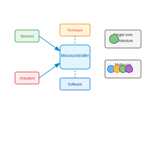
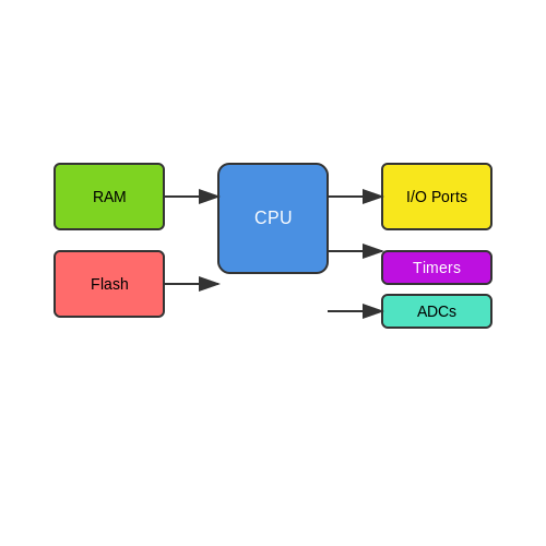
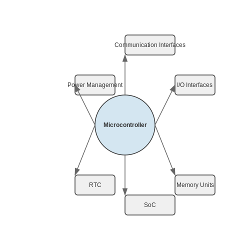
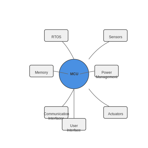
In the realm of aerospace electronics, microcontrollers play a pivotal role in controlling various systems within spacecraft, satellites, and other aerospace applications. These compact integrated circuits are the brains behind many critical functions, offering the power of computation and control in a small package. Let's dive into the basics and architectures of microcontrollers in the context of aerospace engineering. Microcontrollers are essentially small computers on a single integrated circuit comprising a processor core, memory, and peripherals. These devices are designed to execute specific tasks and are widely used in aerospace applications for their reliability and efficiency. The architecture of a microcontroller determines its performance, capabilities, and suitability for different tasks. ### Embedded System Design in Aerospace One of the primary applications of microcontrollers in aerospace is embedded system design. These systems are dedicated to specific functions, such as sensor data processing, actuator control, telemetry, and communication within spacecraft. The efficiency and reliability of embedded systems are crucial in the aerospace industry to ensure the safe operation of vehicles in the harsh environment of space. ### Key Components of Microcontrollers #### 1. Processor Core: - The processor core is the central processing unit (CPU) of the microcontroller responsible for executing instructions. It dictates the processing power and speed of the device. #### 2. Memory: - Microcontrollers include various types of memory, such as ROM (Read-Only Memory) for storing firmware, RAM (Random-Access Memory) for temporary data storage, and EEPROM (Electrically Erasable Programmable Read-Only Memory) for non-volatile data storage. #### 3. Peripherals: - Peripherals are additional components integrated into the microcontroller to facilitate interaction with external devices. These can include analog-to-digital converters (ADCs), timers, communication interfaces (UART, SPI, I2C), and more. ### Microcontroller Architectures Microcontrollers come in different architectures, each suited to specific applications and requirements. Some common architectures used in aerospace electronics include: - Harvard Architecture: This architecture separates the data and instruction buses, allowing simultaneous access to both program memory and data memory. - Von Neumann Architecture: In this architecture, data and instructions share the same memory space, which simplifies the design but can lead to potential bottlenecks. ### Practical Example: Application in Satellite Attitude Control A concrete example of microcontroller use in aerospace is satellite attitude control systems. Microcontrollers within satellites process sensor data to adjust the orientation of the satellite, ensuring precise positioning for communication, imaging, and scientific missions. By understanding the basics and architectures of microcontrollers in aerospace applications, engineers and researchers can leverage these powerful devices to design sophisticated systems for space exploration and satellite operations.{CODE}
3.2 Programming Microcontrollers for Aerospace
In the field of aerospace, microcontrollers play a crucial role in controlling various systems within spacecraft, satellites, and other aerospace devices. Programming microcontrollers for aerospace applications requires a deep understanding of both hardware and software considerations, as reliability and accuracy are paramount.
Mission-Critical Software Design
When programming microcontrollers for aerospace, one of the primary considerations is mission-critical software design. The software must be structured in a way that ensures the safe and reliable operation of the aerospace system under all conditions. This involves developing robust algorithms, implementing fault-tolerant strategies, and designing for high-reliability.
Real-Time Operating Systems (RTOS)
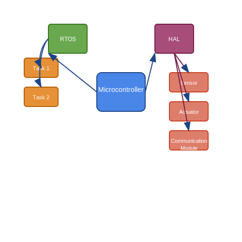
In aerospace applications, real-time operating systems (RTOS) are often utilized to manage tasks and ensure timely execution of critical functions. RTOS provides deterministic behavior, allowing for precise timing and response in time-sensitive operations such as sensor data processing, control algorithms, and communication protocols.
Hardware Abstraction Layer (HAL)
Programming microcontrollers in aerospace also involves the use of hardware abstraction layer (HAL) libraries. HAL provides a standardized interface to interact with the underlying hardware components, enabling portability and facilitating easy migration across different microcontroller platforms without compromising functionality.
Fault Detection and Handling
A key aspect of programming microcontrollers for aerospace is the integration of fault detection and handling mechanisms. These mechanisms are essential for identifying anomalies, diagnosing errors, and implementing corrective actions to maintain system integrity and performance.
Power Management Strategies
Efficient power management is critical in aerospace applications to optimize energy consumption and ensure longevity of battery-powered systems. Programming microcontrollers involves implementing power-saving modes, dynamic voltage scaling, and intelligent power distribution techniques to maximize operational efficiency.
Embedded Communication Protocols
In aerospace systems, microcontrollers often communicate with various subsystems through embedded communication protocols such as CAN (Controller Area Network) or SpaceWire. These protocols are designed for high-reliability data exchange, ensuring robust connectivity and seamless integration of different components within the system.
Conclusion
Programming microcontrollers for aerospace applications requires a comprehensive approach that combines high-level software design principles with stringent hardware constraints. By incorporating fault-tolerant strategies, efficient power management, and reliable communication protocols, engineers can develop software solutions that meet the demanding requirements of the aerospace industry.
3.3 Real-Time Operating Systems in Embedded Aerospace
Real-time operating systems (RTOS) play a crucial role in embedded aerospace systems where strict timing requirements are essential for mission-critical applications. These specialized operating systems are optimized for deterministic behavior, ensuring tasks are completed within precise time constraints.
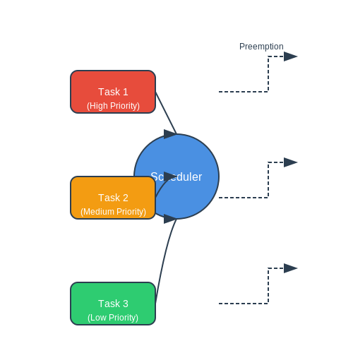
One key feature of RTOS in aerospace applications is their ability to manage tasks with varying priorities efficiently. Tasks are assigned priority levels, and the RTOS scheduler ensures that higher priority tasks preempt lower priority ones, guaranteeing timely execution of critical functions.
RTOS kernels often provide features such as task synchronization mechanisms (semaphores, mutexes) and inter-process communication facilities (message queues) to allow efficient coordination between different tasks running on the system.
Practical Applications in Aerospace
The utilization of RTOS in aerospace extends to a wide range of applications:
- Flight Control Systems: RTOS ensures real-time response for controlling aircraft systems, enhancing stability and safety during flight.
- Satellite Systems: RTOS manages communication, data processing, and payload control in satellites, enabling precise operation in space.
- Navigation Systems: RTOS supports accurate positioning and navigation computations, critical for aircraft and spacecraft guidance.
RTOS Scheduling Algorithms
RTOS employs various scheduling algorithms to allocate processor time to different tasks. Common scheduling algorithms include:
- Fixed Priority Pre-emptive Scheduling: Tasks are assigned fixed priorities, and the scheduler always selects the highest priority task for execution.
- Rate-Monotonic Scheduling: Tasks with shorter periods are assigned higher priorities to ensure timely completion. This is suitable for periodic tasks in time-critical systems.
RTOS Kernel Design
The design of an RTOS kernel is critical for its performance and reliability in aerospace applications. Key considerations in RTOS kernel design include:
- Minimal Footprint: RTOS must be efficient in terms of memory usage and processing overhead to meet the stringent resource constraints of embedded systems in aerospace.
- Deterministic Behavior: Predictability in task execution timing is essential to prevent system failures and ensure mission success in aerospace operations.
4. Types of Sensors Used in Aircraft
Types of Sensors Used in Aircraft
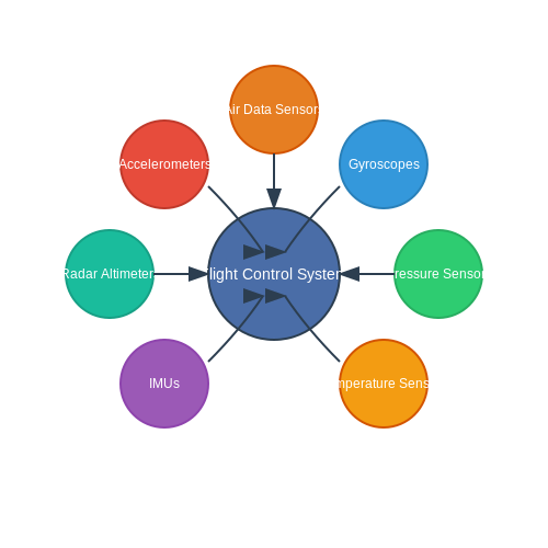
In the aerospace industry, various sensors play critical roles in providing vital information for safe and efficient operation of aircraft. These sensors are utilized across different systems within an aircraft to ensure performance, safety, and reliability in various conditions.
1. Accelerometers
Accelerometers are used to measure the acceleration forces experienced by an aircraft. They are crucial in flight control systems for detecting changes in speed and direction. Capacitive, piezoelectric, and piezoresistive accelerometers are commonly employed in aircraft to facilitate precise measurement of accelerations.
2. Gyroscopes
Gyroscopes provide angular rate information about the aircraft's orientation in space. MEMS gyroscopes have become popular due to their small size and high accuracy. They are essential for attitude control, navigation systems, and stability augmentation in aircraft.
3. Pressure Sensors
Pressure sensors are utilized to measure altitude, airspeed, and cabin pressure in aircraft. Barometric pressure sensors and pitot tubes are commonly used for calculating altitude and airspeed, while pressure transducers monitor cabin pressure, ensuring passenger comfort and safety.
4. Temperature Sensors
Temperature sensors are crucial for monitoring engine temperature, cabin temperature, and critical components in an aircraft. Thermocouples and resistance temperature detectors (RTDs) are frequently employed due to their accuracy and reliability in extreme conditions.
5. Inertial Measurement Units (IMUs)
IMUs combine accelerometers and gyroscopes to provide comprehensive motion sensing capabilities. They are pivotal in navigation systems, flight control, and autopilot systems. IMUs offer real-time data on an aircraft's position, velocity, and orientation.
6. Radar Altimeters
Radar altimeters determine an aircraft's altitude above the terrain by transmitting and receiving radio waves. They are crucial for low-altitude flight, landing approaches, and terrain avoidance. Radar altimeters enhance safety during takeoff and landing by providing accurate altitude readings.
7. Air Data Sensors
Air data sensors measure various parameters such as airspeed, angle of attack, and side slip angle. These sensors are integral for flight instrumentation, autopilot systems, and flight performance monitoring. Air data sensors ensure precise control and navigation during flight.
By leveraging an array of sensors designed for specific functions, modern aircraft achieve unparalleled levels of safety, efficiency, and performance.
4.2 Data Acquisition Systems
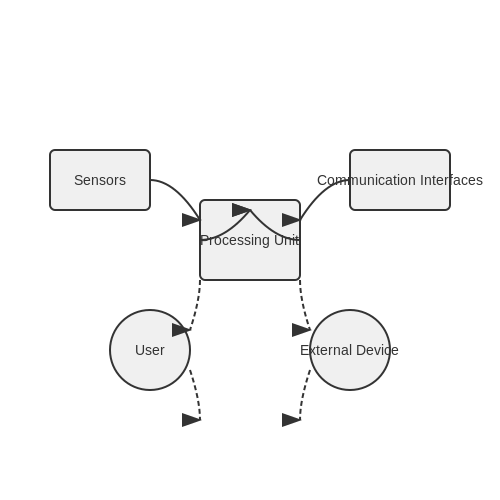
In the realm of Aerospace Electronics, data acquisition systems play a crucial role in collecting, processing, and transmitting data from various sensors and instruments. These systems are designed to gather real-time information about the aircraft's performance, environmental conditions, and other essential parameters. Let's delve into the intricacies of data acquisition systems in aerospace applications. ### Introduction to Data Acquisition Systems Data acquisition systems in aerospace are highly sophisticated setups that consist of sensors, signal conditioning components, analog-to-digital converters (ADCs), data processing units, and communication interfaces. These systems are employed to gather data from multiple sources, convert analog signals to digital data, process it in real-time, and finally store or transmit it for analysis. ### Components of Data Acquisition Systems 1. Sensors: These are the primary input devices that measure physical phenomena such as pressure, temperature, acceleration, and more. 2. Signal Conditioning: This stage involves amplifying, filtering, and isolating the raw sensor signals to ensure accuracy and reliability. 3. Analog-to-Digital Conversion (ADC): The analog signals from the sensors are converted into digital data for processing and storage. 4. Data Processing Unit: This component processes the digitized data, applying algorithms and logic to extract valuable information. 5. Communication Interfaces: These interfaces facilitate the transmission of data to various onboard systems or to ground control. ### Operation of Data Acquisition Systems The functioning of a data acquisition system involves the following steps: 1. Sampling: The system samples the analog input signals at regular intervals to capture the data accurately. 2. Quantization: The analog signals are converted into discrete digital values through the process of analog-to-digital conversion. 3. Data Processing: The digital data is processed in real-time to derive meaningful insights or trigger specific actions. 4. Data Storage/Transmission: Processed data is either stored within the system or transmitted to external devices for further analysis. ### Real-world Applications Data acquisition systems find widespread use in aerospace for: - Monitoring aircraft performance parameters. - Analyzing structural health and integrity. - Collecting data for research and development purposes. - Ensuring the safety and efficiency of flight operations. ### Mathematical Derivation Let's consider the basic equation for analog-to-digital conversion: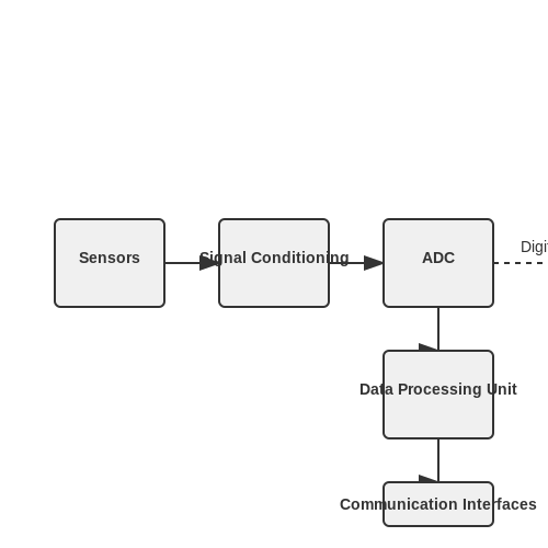
Signal Processing Techniques
Signal processing plays a crucial role in aerospace electronics, enabling the analysis, manipulation, and interpretation of signals to extract meaningful information. In this section, we will delve into advanced signal processing techniques used in aerospace applications.
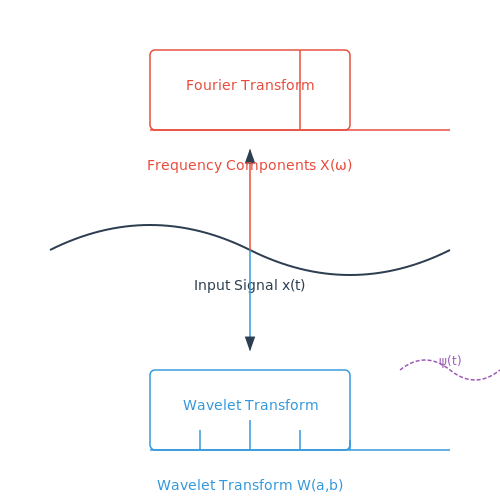
Fourier Transform
One of the fundamental tools in signal processing is the Fourier Transform. It decomposes a signal into its frequency components, revealing the frequency content of the signal. Mathematically, the Fourier Transform of a continuous-time signal x(t) is defined as:
The Fourier Transform allows us to analyze signals in the frequency domain, aiding in filtering, modulation, and spectral analysis in aerospace systems.
Filtering Techniques
Filters are essential in signal processing to remove unwanted noise, extract specific features, or enhance signal quality. Aerospace applications often require advanced filtering techniques such as:
- Butterworth Filter: A type of signal processing filter with a maximally flat frequency response.
- Chebyshev Filter: An efficient filter design for applications with specific ripple requirements.
- Elliptic Filter: Providing a steeper roll-off and improved selectivity compared to other filter types.
Proper filter design and implementation are crucial for ensuring signal fidelity and reducing interference in aerospace communication and control systems.
Wavelet Transform
The Wavelet Transform is another powerful signal processing tool that offers both time and frequency localization. Unlike the Fourier Transform, which provides frequency information but loses temporal details, the Wavelet Transform captures local variations in both time and frequency domains.
Mathematically, the continuous Wavelet Transform of a signal x(t) is given by:
where $$\psi(t)$$ is the analyzing wavelet function, $$a$$ represents dilation, and $$b$$ is the translation parameter.
The Wavelet Transform finds applications in radar signal processing, image compression, and anomaly detection in aerospace systems.
Adaptive Signal Processing
Adaptive signal processing techniques, such as adaptive filters and algorithms, allow system parameters to adjust in real-time to changing signal conditions. These algorithms optimize performance in dynamic aerospace environments by continuously adapting to variations and disturbances.
Key adaptive signal processing methods include the LMS (Least Mean Squares) algorithm and the NLMS (Normalized Least Mean Squares) algorithm, which are widely used in aerospace communication systems for echo cancellation, interference suppression, and channel equalization.
Practical Applications
The signal processing techniques discussed have diverse applications in aerospace systems:
- Fourier Transform is used in spectrum analysis of radar signals.
- Filtering techniques enhance the quality of telemetry data in satellite communications.
- Wavelet Transform aids in fault detection in aircraft sensors.
- Adaptive signal processing algorithms improve speech clarity in aircraft communication systems.
Understanding and implementing these signal processing techniques are vital for advancing aerospace technology and ensuring reliable and efficient operation of aerospace electronic systems.
5. Power Distribution Systems
Power Distribution Systems
Power distribution systems in aerospace play a critical role in ensuring reliable and efficient operation of various electronic components. These systems need to meet stringent requirements in terms of voltage regulation, power efficiency, and fault tolerance. Let's delve into the key aspects of power distribution systems in aerospace applications.Voltage Regulation in Aerospace Systems
In aerospace applications, maintaining a stable voltage supply is of utmost importance to ensure the proper functioning of electronic systems. Voltage regulators are commonly used to stabilize the voltage levels supplied to critical components such as avionics, communication systems, and flight control systems. These regulators actively adjust the output voltage to counter fluctuations in input voltage, load variations, and temperature changes.Power Efficiency and Loss Mitigation
Efficient power distribution is crucial in aerospace systems to minimize energy wastage and optimize overall system performance. Power loss in transmission lines can be mitigated by employing high-efficiency power converters and carefully designing the power distribution network. Techniques such as voltage conversion, current limiting, and impedance matching are utilized to enhance power efficiency and reduce unnecessary power dissipation.Fault Tolerance and Redundancy
Aerospace systems often incorporate redundant power distribution paths to ensure continued operation in the event of a component failure or power supply interruption. Redundant power systems can be implemented at various levels, from individual circuit boards to entire subsystems, to enhance fault tolerance and increase system reliability. Automatic switchover mechanisms and fault detection algorithms are employed to seamlessly transition between primary and backup power sources.Real-World Applications
The concepts of voltage regulation, power efficiency, and fault tolerance are not abstract theories but have practical implications in real-world aerospace applications. For instance, in satellite systems, power distribution systems must be designed to withstand the harsh radiation environment of space while ensuring continuous power supply to critical onboard electronics. Similarly, in aircraft avionics, stringent regulations govern the design and implementation of power distribution systems to ensure safe and reliable operation under all conditions.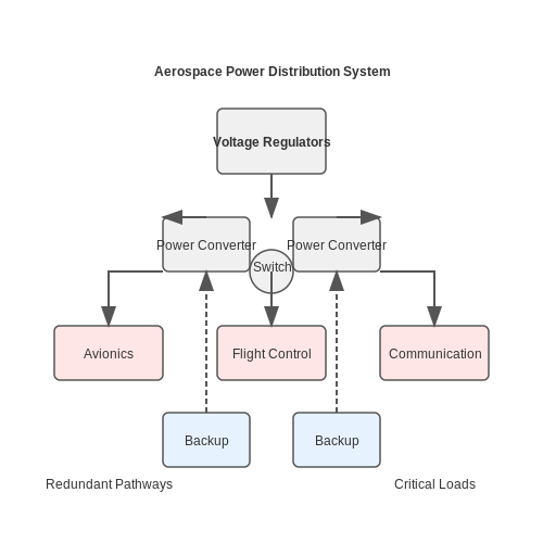
def calculate_remaining_capacity(voltage, current, temperature):
    # Use advanced algorithms to estimate remaining battery capacity
    estimated_capacity = voltage * current / temperature
    return estimated_capacity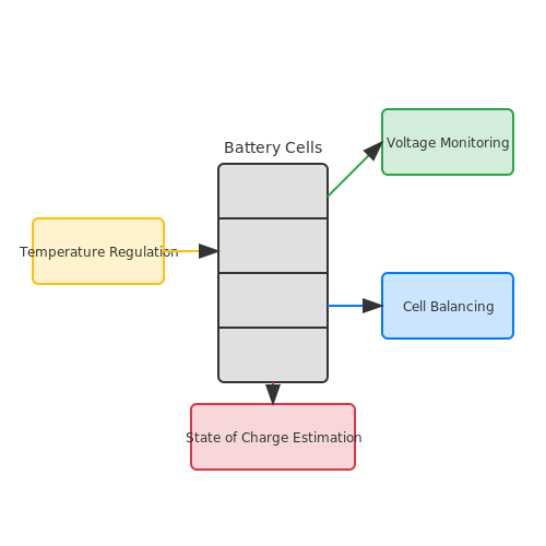
5.3 Energy Harvesting Techniques
Energy harvesting techniques play a crucial role in aerospace applications where power sources are limited or inaccessible. This subsection explores various methods used to harvest energy from the environment to power onboard systems efficiently.
Piezoelectric Energy Harvesting
Piezoelectric materials convert mechanical strain into electrical energy and are commonly used in aerospace for vibration-based energy harvesting. The principle relies on the generation of electrical charge due to mechanical deformation.
Thermoelectric Energy Harvesting
Thermoelectric generators utilize the temperature difference between the aerospace vehicle and its surroundings to generate electricity. The Seebeck effect is the cornerstone of this technology, where a voltage is created across a temperature gradient.
Solar Energy Harvesting
Solar panels are extensively used in aerospace to convert sunlight into electrical energy. These panels consist of photovoltaic cells that generate electricity when exposed to sunlight, providing a renewable and sustainable power source for spacecraft and satellites.
Radioisotope Thermoelectric Generators (RTGs)
RTGs utilize the heat produced by the radioactive decay of isotopes to generate electrical power. While primarily used in deep-space missions where sunlight is scarce, RTGs are a reliable and long-lasting energy source for aerospace applications.
# Python code example here 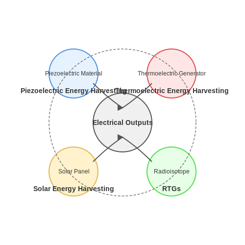
6. Failure Modes and Effects Analysis
6.1 Failure Modes and Effects Analysis
In the context of electronics for aerospace, Failure Modes and Effects Analysis (FMEA) is a crucial technique employed to identify and analyze potential failure modes within a system, component, or process. This method allows engineers to proactively address potential issues, enhance reliability, and improve overall safety in aerospace electronics. FMEA is typically conducted in a structured manner, involving the following key steps: 1. Identification of Components: Begin by identifying all components within the electronic system that are critical to its operation or safety. 2. Analysis of Failure Modes: For each identified component, analyze the potential failure modes that could occur. This includes electrical failures, mechanical failures, environmental damage, and more. 3. Assessment of Failure Effects: Evaluate the effects of each failure mode on the overall system performance, safety, and mission success. Consider the severity of these effects and their potential consequences. 4. Assigning Risk Priorities: Assign a risk priority number (RPN) to each failure mode based on factors such as severity, likelihood of occurrence, and detectability. This allows for prioritization of mitigation efforts. 5. Developing Mitigation Strategies: Once the critical failure modes are identified and prioritized, engineers can develop mitigation strategies to reduce the likelihood of occurrence or minimize the impact of potential failures. 6. Implementation and Monitoring: Implement the identified mitigation strategies and continuously monitor the system for any emerging issues. Regular reviews and updates to the FMEA are essential to maintaining system reliability. By systematically applying FMEA in the design, development, and operation of aerospace electronics, engineers can enhance system reliability, robustness, and safety in complex and dynamic environments. ---### References and Further Reading
- NASA - Failure Analysis — Explore NASA's extensive resources on failure analysis techniques used in aerospace engineering.
- SAE International - FMEA Guidelines — Access the FMEA guidelines provided by SAE International for aerospace applications.
- IEEE Xplore - Reliability Analysis — IEEE Xplore offers insights into reliability analysis methods for aerospace electronics.
- ASME - Risk Assessment — Explore the ASME resources on risk assessment techniques relevant to aerospace systems.
- Defense Acquisition University - FMEA Training — Discover training programs on FMEA specifically tailored for aerospace and defense applications.
- FAA - Safety Management System — Access information on safety management systems in aerospace, including failure analysis techniques.
- DAU - Systems Engineering Fundamentals — Dive into systems engineering fundamentals related to aerospace electronics reliability.
6.2 Reliability Testing Methods
In the field of aerospace electronics, ensuring reliability is paramount due to the critical nature of components used in aircraft, satellites, and spacecraft. Reliability testing methods play a crucial role in validating the performance and longevity of electronic systems in these high-stakes applications. ####Accelerated Life Testing
Accelerated life testing involves subjecting electronic components or systems to stress conditions beyond their normal operating parameters to accelerate the aging process. By simulating harsh environmental conditions such as temperature extremes, vibration, and voltage spikes, engineers can predict the behavior of components over an extended period in a shorter time frame. This method helps in identifying potential failure modes early on and proactively improving design robustness.Fault Injection Testing
Fault injection testing involves intentionally introducing faults or errors into a system to observe its response and determine its robustness against unexpected events. By systematically injecting faults such as voltage fluctuations, signal noise, or component failures, engineers can evaluate how well the system responds and recovers from these disturbances. This testing method is particularly valuable for assessing the fault-tolerance of critical aerospace systems. ####Reliability Block Diagrams
Reliability block diagrams provide a graphical representation of system reliability by breaking down complex systems into individual components or modules connected in a series, parallel, or redundant configuration. By analyzing the reliability contributions of each block and determining the overall system reliability, engineers can identify critical components that may need redundancy or further testing to improve the system's reliability.Environmental Stress Screening (ESS)
Environmental stress screening involves subjecting electronic systems to a series of thermal cycling and vibration tests to identify latent defects that may cause failures in the field. By exposing the system to rapid temperature changes and mechanical stresses, ESS helps in detecting and eliminating weak components that could fail under normal operating conditions. This method significantly improves the overall reliability of aerospace electronics. By employing these reliability testing methods, aerospace engineers can ensure the robustness and dependability of electronic systems used in critical aerospace applications, thereby enhancing safety and mission success in the aerospace industry.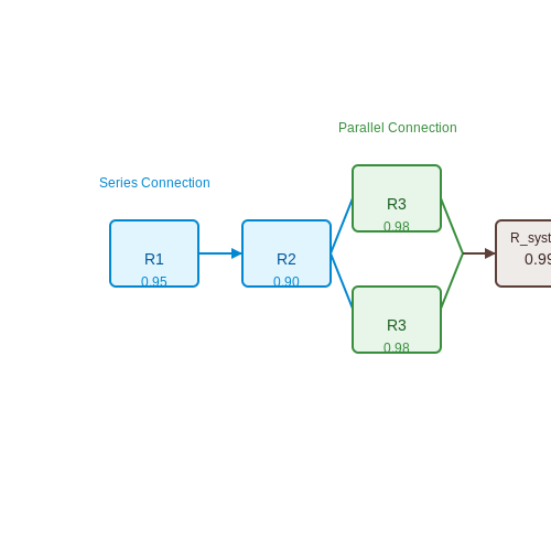
Regulatory Standards for Aerospace Systems
In the realm of aerospace electronics, adherence to stringent regulatory standards is paramount to ensure the safety, reliability, and efficiency of systems operating in demanding environments. This section delves into the key regulatory frameworks and standards that govern electronics within the aerospace industry.
Regulatory Bodies
Several regulatory bodies play a vital role in setting standards and guidelines for aerospace electronics. The European Aviation Safety Agency (EASA) and the Federal Aviation Administration (FAA) in the United States are two prominent organizations that establish regulations to maintain the airworthiness of aerospace systems. These bodies ensure that electronic components meet rigorous safety and performance criteria, aligning with the unique requirements of the aerospace sector.
DO-178C Software Considerations
One crucial standard in aerospace electronics is DO-178C, which outlines guidelines for the development of safety-critical software used in airborne systems. This standard establishes rigorous objectives for software development processes, verification, and validation to achieve the highest levels of reliability and safety in aerospace applications.
EMC and EMI Compliance
Electromagnetic Compatibility (EMC) and Electromagnetic Interference (EMI) compliance are essential for aerospace electronics to ensure that systems can operate reliably in the presence of electromagnetic disturbances. Compliance with standards such as RTCA/DO-160 ensures that aerospace equipment can withstand and operate in electromagnetic environments encountered during flight.
Environmental Testing
Environmental testing standards, such as RTCA/DO-160, define the requirements for verifying the resilience of aerospace electronics to extreme conditions including temperature variations, humidity, shock, and vibration. These standards ensure that electronic components can withstand harsh environmental factors commonly experienced during aerospace operations.
7. Autonomous Systems and Artificial Intelligence
7.1 Autonomous Systems and Artificial Intelligence
In the realm of aerospace electronics, autonomous systems coupled with artificial intelligence (AI) play a pivotal role in enhancing the capabilities of spacecraft, satellites, and unmanned aerial vehicles. These systems enable automated decision-making, navigation, and control, revolutionizing the way we explore and interact with the aerospace environment.
Autonomous Systems in Aerospace
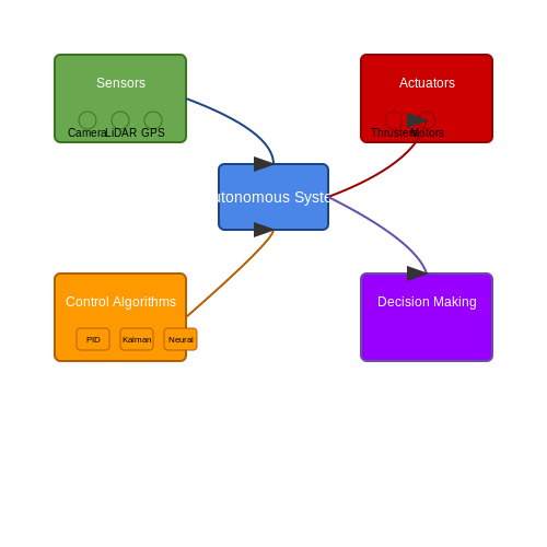
Autonomous systems refer to self-governing mechanisms that can operate without direct human intervention. In aerospace applications, these systems are crucial for tasks such as trajectory planning, obstacle avoidance, and adaptive control. They rely on a combination of sensors, actuators, and sophisticated algorithms to interpret data and make informed decisions in real-time.
Key Components:
- Sensors: Autonomous aerospace systems utilize a variety of sensors including cameras, LiDAR, GPS, accelerometers, and gyroscopes to gather information about the surrounding environment.
- Actuators: These are responsible for executing commands based on the decisions made by the autonomous system. Examples include thrusters for attitude control and motors for propulsion.
- Control Algorithms: Advanced control strategies such as PID controllers, Kalman filters, and neural networks are employed to ensure precise and reliable operation of the autonomous system.
Artificial Intelligence (AI) in Aerospace
Artificial intelligence, specifically machine learning algorithms, empowers aerospace electronics to learn from data, adapt to changing conditions, and improve performance over time. AI is integrated into autonomous systems to enhance decision-making capabilities, optimize efficiency, and enable autonomous learning.
Applications of AI in Aerospace:
- Autonomous Navigation: AI algorithms enable spacecraft and satellites to navigate complex trajectories, avoid collisions, and dock with precision.
- Health Monitoring: AI can predict component failures, detect anomalies in real-time, and recommend maintenance actions to ensure the reliability of aerospace systems.
- Mission Planning: AI is utilized to optimize mission parameters, resource allocation, and scheduling for efficient utilization of aerospace assets.
Advancements & Future Prospects
The integration of autonomous systems and AI in aerospace continues to evolve rapidly, driven by advancements in sensor technology, computing power, and algorithm design. Future applications include autonomous space exploration missions, AI-enhanced satellite networks, and unmanned aerial systems with adaptive learning capabilities.
7.2 Advanced Materials and Manufacturing Techniques
Advanced materials and manufacturing techniques play a pivotal role in the development of electronics for aerospace applications. In this section, we delve into the cutting-edge advancements that enable the creation of robust and high-performance electronic components for use in aerospace systems.
Material Selection in Aerospace Electronics
The stringent requirements in aerospace electronics demand the use of materials that exhibit exceptional properties such as high thermal stability, low coefficient of thermal expansion, excellent electrical conductivity, and resistance to radiation damage. Composite materials, such as carbon fiber reinforced polymers and ceramic matrix composites, have gained popularity due to their lightweight nature and superior mechanical properties.
Composite Materials in Aerospace Electronics
Composite materials offer a unique combination of properties that make them ideal for aerospace applications. By carefully selecting the composition and structure of composites, engineers can tailor the material properties to meet specific requirements. Advanced manufacturing techniques, such as automated fiber placement and resin transfer molding, are used to fabricate complex composite structures with high precision and repeatability.
Manufacturing Techniques for Aerospace Electronics
The manufacturing of electronic components for aerospace applications requires specialized techniques to ensure reliability and performance under extreme conditions. Additive manufacturing, also known as 3D printing, has revolutionized the production of complex geometries with reduced lead times. Selective laser sintering and electron beam melting are commonly used additive manufacturing methods to create intricate metal components with high accuracy.
Microfabrication in Aerospace Electronics
Microfabrication techniques, such as photolithography and thin-film deposition, are employed to produce miniaturized electronic devices for aerospace systems. These processes enable the creation of ultra-compact components with precise features, essential for reducing weight and optimizing space utilization in space-bound electronics.
By integrating advanced materials and manufacturing techniques, aerospace engineers can design electronic systems that are not only reliable and robust but also lightweight and capable of withstanding the harsh environments of space. The continual advancements in materials science and manufacturing technologies are driving innovation in aerospace electronics, shaping the future of space exploration and satellite communications.
7.3 The Role of IoT in Aerospace
In the realm of aerospace, the integration of Internet of Things (IoT) technologies has revolutionized various aspects of operations, maintenance, and monitoring. IoT refers to the network of physical devices, vehicles, and other items embedded with sensors, software, and connectivity to enable them to collect and exchange data. IoT in the aerospace sector serves critical functions, enhancing efficiency, safety, and data-driven decision-making. Let's explore some key roles of IoT in Aerospace:1. Condition Monitoring and Predictive Maintenance
One pivotal application of IoT in aerospace is condition monitoring of aircraft components in real-time. By equipping aircraft engines, landing gear, and other critical parts with sensors, data on performance and wear can be continuously collected. This data is then analyzed to predict potential failures before they occur, leading to proactive maintenance scheduling and enhancing overall safety.2. Fleet Management and Optimization
IoT enables comprehensive tracking and optimization of aircraft fleets. Data on flight routes, fuel consumption, weather conditions, and engine performance can be gathered and analyzed to optimize operational efficiency, reduce fuel costs, and minimize downtime. Real-time monitoring allows for dynamic adjustments during flights to adapt to changing conditions.3. Enhanced Flight Safety
By integrating IoT devices within aircraft systems, real-time monitoring of crucial parameters such as altitude, speed, and engine performance is facilitated. In the event of anomalies or emergencies, automated alerts can be generated to the cockpit crew or ground control, enabling rapid response. This proactive safety approach significantly reduces the risk of accidents.4. Data Analytics for Performance Optimization
The vast amount of data collected through IoT devices on aircraft operations allows for sophisticated data analytics. By leveraging machine learning algorithms and predictive models, airlines can optimize flight routes, fuel efficiency, and overall performance. This data-driven approach not only enhances operational efficiency but also reduces environmental impact.Conclusion
In conclusion, IoT plays a pivotal role in transforming aerospace operations by providing real-time data insights, predictive maintenance capabilities, enhanced safety measures, and improved efficiency. The integration of IoT technologies continues to revolutionize the aerospace industry, paving the way for smarter, more interconnected aircraft systems.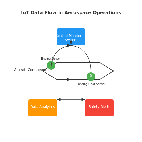
8. Recommended Texts and Journals
8.1 Recommended Texts and Journals
- IEEE Aerospace and Electronic Systems Society — A leading platform providing extensive journals and publications related to aerospace and electronics, including pioneering research and case studies.
- AIAA - American Institute of Aeronautics and Astronautics — Offers a wide range of journals and conference papers focusing on aerospace science and technology. Ideal for cutting-edge research articles.
- Aerospace Science and Technology — An Elsevier journal delivering contemporary research in aerospace, emphasizing innovation and developments in electronic systems.
- IEEE Xplore Digital Library — An extensive digital library providing access to technical literature in electrical engineering, computer science, and aerospace systems.
- ScienceDirect: Aerospace Science and Technology Journal — Publishes high-quality research articles covering both theoretical and practical aspects of aerospace technologies.
- Journal of Electronic Engineering — Focuses on electronic circuits and systems applications, highly relevant for engineers involved in aerospace electronics.
- ASME Journal of Autonomous Vehicles and Systems — Provides insights into the development and application of autonomous vehicular systems, important for aerospace innovations.
- The International Journal of Advanced Manufacturing Technology — Highlights advancements in aerospace manufacturing processes and control systems, essential for new material insights.
- Audio Engineering Society (AES) — While primarily focused on audio, it covers tech innovations applicable to communication systems in aerospace applications.
- IET Control Theory & Applications — A resource on control systems engineering, beneficial for aerospace control system design and implementation.
- Publications of the Astronomical Society of Japan — Although more focused on astronomy, its technology reviews often explore aerospace electronics' role in instrumentation.
8.2 Online Resources and Courses
In the rapidly evolving field of aerospace electronics, continually updating your knowledge is essential. A plethora of online resources and courses is available to help you gain deeper insights and stay current with the latest technological advancements. Below is a curated list of high-quality online resources that provide comprehensive learning opportunities and materials for advanced learners in this domain.
- Coursera - Introduction to Electronics — This specialization covers the basics of electronics, essential for understanding advanced concepts in aerospace applications. The course includes exhaustive modules on circuits, semiconductor devices, and microelectronics.
- edX - MITx MicroMasters Program in Principles of Manufacturing — This program dives into the complexities of manufacturing systems, critical for aerospace electronics production, offering insights into design principles, production dynamics, and control systems.
- MIT OpenCourseWare - Introduction to EECS I — Provides a foundational understanding of electrical engineering and computer science, crucial for developing robust aerospace electronics. The course includes video lectures, problem sets, and thorough explanatory notes.
- Electronics Point — A forum rich with expert discussions, problem-solving threads, and DIY projects related to aerospace electronics. Join the community to share insights and gain knowledge from experienced engineers and enthusiasts.
- NASA Online Learning — Features a collection of NASA's educational resources focusing on aerospace technologies. Includes interactive modules and detailed information about electronics used in current space missions and projects.
- Khan Academy - Physics — While not exclusively for aerospace, this platform offers numerous modules on physics principles that underlie electronic systems in aerospace technology, making it a valuable supplemental resource.
- Udacity - Intro to Programming Nanodegree — Equips learners with essential programming skills needed for developing and managing software in aerospace electronics projects. This course includes Python and C++ programming, relevant for embedded systems.
8.3 Industry Standards and Best Practices
In aerospace electronics, adherence to industry standards and best practices is crucial for ensuring safety, reliability, and performance. This section delves into key standards that govern the field and highlights essential best practices adopted by professionals to meet these standards. Through a combination of historical context and practical relevance, this section provides a comprehensive overview of the frameworks essential to mastering aerospace electronics.
Aerospace Standards Overview
Historically, aerospace standards originated from the need to ensure reliability and interoperability in the complex systems employed in air and space travel. Among the critical standards organizations are the Institute of Electrical and Electronics Engineers (IEEE) and the Radio Technical Commission for Aeronautics (RTCA). For example, the DO-160 by RTCA is a standard that specifies the environmental conditions and test procedures for airborne equipment. It is widely accepted for testing avionics hardware to ensure resilience against various environmental factors such as temperature, vibration, and electromagnet interference.
DO-178C: Software Considerations
The DO-178C standard, developed by RTCA, is another cornerstone for software development in aerospace. It outlines guidelines for the Certification of Airborne Systems and Equipment, ensuring that software operates correctly under all foreseeable operating conditions. This includes documenting the software development lifecycle, establishing verification and validation protocols, and ensuring traceability between requirements and testing outcomes.
Mathematical Modeling and Validation
Validation processes involve rigorous testing through mathematical modeling, which ensures predictive accuracy and reliability. For example, a dynamic system can be expressed mathematically by defining its state-space representation. This allows simulation models to predict behavior accurately, promoting both understanding and validation of the theoretical framework:
Where x(t) is the state vector, u(t) is the input vector, y(t) is the output vector, and A, B, C, D are matrices representing the system's properties. Adhering to these principles is critical for professionals tasked with ensuring that software and hardware conform to rigorous aerospace standards.
Best Practices for Aerospace Electronics
To comply with these standards, best practices in aerospace electronics revolve around methodical design processes, comprehensive testing, and risk management. Key strategies include:
- Design for Redundancy: Aims to add backup systems to minimize single points of failure, ensuring that a fault in one system does not compromise the entire mission.
- System Integration Testing: Involves thorough testing of integrated systems in simulated environments that mimic real-world conditions, identifying and mitigating potential issues early in the development cycle.
- Lifecycle Management: Incorporates processes to manage the complete lifecycle of electronic components, from initial design through production to decommissioning, ensuring that each phase complies with the latest industry standards.
Such strategic practices not only ensure compliance with existing standards but also enhance system robustness and reliability, two key attributes in aerospace engineering. By integrating these best practices, engineers and researchers can anticipate potential issues and innovate effectively in the face of cutting-edge challenges.