Applied Autotransformers
1. Definition and Basic Principles
1.1 Definition and Basic Principles
Applied autotransformers are a critical component in the field of electrical engineering and power systems. They are unique in that they combine the functionality of a transformer with a more efficient means of voltage transformation. Conventionally, transformers consist of two separate windings; however, in an autotransformer, a single winding serves the purpose of both the primary and secondary circuits. This structural distinction leads to some significant operational advantages.
At the heart of an autotransformer's design is the principle of electromagnetic induction. When an alternating current flows through the primary winding, it generates a magnetic field that induces a voltage in the secondary part of the same winding. The division of the winding into sections allows for a variable output voltage, which can be adjusted based on the turns ratio of the connection.
The turns ratio, denoted as n, is a crucial factor for determining output voltage. This ratio is defined as:
where N1 is the number of turns in the portion of the winding connected to the source voltage and N2 is the number of turns connected to the load. Consequently, the secondary voltage V2 can be expressed in relation to the primary voltage V1:
The autotransformer is particularly appealing for applications requiring moderate voltage variations, exemplified by applications in induction heating, motor starting circuits, and specialized power supplies. Its compact design leads to fewer material costs and reduced weights compared to conventional transformers, making them indispensable in various engineering projects.
Another significant aspect of autotransformers is their efficiency. Because of the shared winding, they exhibit lower copper losses and can handle higher power ratings for compact designs. Therefore, they are prevalent in industrial settings and power distribution systems, where efficiency translates to reduced operational costs.
However, it is crucial to mention that autotransformers are typically less isolated than traditional transformers. The absence of galvanic isolation can pose risks in certain settings, particularly where safety is paramount. This characteristic limits their application in isolation-required scenarios, underscoring the importance of understanding the practical implications of their use.
This practical relevance is further underscored when considering historical applications—such as in the early days of electrical distribution where autotransformers facilitated voltage adjustments during transmission, leading to efficiencies that powered expanding infrastructures.
Thus, the applied autotransformer stands out as a vital device in electrical systems, marrying the principles of electromagnetism with practical engineering applications, unlocking opportunities across various industrial and technological landscapes.

1.2 Types of Autotransformers
In the realm of electrical engineering, autotransformers serve as a specialized class of transformers with distinct operational efficiencies and characteristics. Understanding the various types of autotransformers can enhance the application of these devices in practical settings, significantly impacting system design and cost-efficiency. Autotransformers are often classified based on their phase configuration, tap arrangement, and functionality. Let's delve into each type to grasp their unique advantages and constraints.Single-Phase Autotransformers
Single-phase autotransformers are primarily utilized in residential and small commercial applications. They consist of a single winding, serving both as the primary and the secondary, divided into two voltage sections. The ability to step up or step down voltage with minimal losses makes them exceptionally efficient for applications where size and cost are critical. For instance, in a single-phase autotransformer used for lighting applications, an engineer can employ the device to reduce the voltage from 230V to 110V efficiently, optimizing energy usage in the process. These transformers are characterized by low copper losses and reduced core materials, resulting in a compact form relative to traditional transformer designs.Key Features
- Efficiency: Typically over 95% due to reduced copper and core losses.
- Compact Size: Smaller than conventional transformers with equivalent ratings.
- Cost-Effective: Lower material costs due to reduced copper usage.
Three-Phase Autotransformers
When it comes to industrial applications, three-phase autotransformers are indispensable. They consist of three single-phase autotransformer units interconnected to provide balanced power across three phases. These transformers are primarily used for industrial voltage regulation and motor applications, accommodating various voltage levels. In a three-phase system, the configuration allows for enhanced voltage management, reducing the need for multiple single-phase units. For example, in a manufacturing facility, a three-phase autotransformer can step down the supply voltage from 400V to 230V for specific machinery, ensuring consistent operations and prolonging equipment lifespan.Advantages of Three-Phase Autotransformers
- Reduced Cost: More economical than using separate three-phase transformers.
- Improved Performance: Balanced loading across phases minimizes losses.
- Versatile Applications: Ideal for large motors and high-power circuits.
Variable Autotransformers
A variable autotransformer, commonly known as a Variac, allows for adjustable output voltage. This design is particularly advantageous for laboratory testing and applications requiring voltage manipulation, such as in testing electrical equipment or calibrating devices. By modifying the tap point on the winding, users can obtain a range of output voltages as required. Engineers often use variable autotransformers in educational settings to demonstrate electrical principles or in industrial calibration processes to ensure that instruments remain within specified operational ranges.Applications of Variable Autotransformers
- Laboratory Testing: Provides a controlled environment for testing components.
- Motor Speed Control: Adjusts voltage to vary motor speed in a controlled manner.
- Research and Development: Facilitates experimentation with different voltage levels for experimental setups.
Applications in Power Systems
Autotransformers find substantial applications within power systems, particularly in conditions where efficient energy transfers and voltage regulation are paramount. Their ability to handle high loads while maintaining compact dimensions allows for implementation in substations and transmission lines, thereby reducing installation costs and enhancing operational efficiency. As the demand for sustainable energy solutions increases, the knowledge of different types of autotransformers enables engineers to develop smarter and more efficient power systems, paving the way for future advancements in electrical engineering. In summary, the various types of autotransformers cater to specific needs based on their design configurations, providing essential versatility and efficiency for a wide range of industrial and laboratory applications. Utilizing the right type of autotransformer not only maximizes performance but also leads to economic advantages in energy consumption and material usage.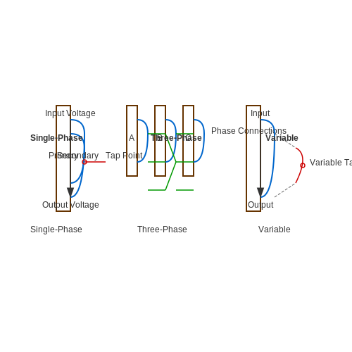
1.3 Construction and Design Features
Introduction to Autotransformer Design
Autotransformers are pivotal in applications requiring electrical energy transformation with optimal efficiency and minimal material use. Unlike traditional transformers, which have separate primary and secondary windings, an autotransformer incorporates a single winding that serves as both. This configuration presents distinct construction and design features that influence performance and applications, making it essential for professionals in the field to comprehend these intricacies.
Core Construction and Materials
At the heart of any electrical transformer lies its core, which substantially impacts efficiency, performance, and overall design. Autotransformer cores are typically constructed using silicon steel laminations, which serve to reduce energy losses due to eddy currents. The use of laminated cores also maintains magnetic integrity, reducing hysteresis losses that can occur within the material.
The core configuration can follow either a laminated or toroidal design. Laminated designs are prevalent due to ease of manufacturing, while toroidal cores offer advantages in reducing magnetic flux leakage and improving space efficiency. The choice between these designs can be dictated by factors such as weight constraints, cost, and intended application (e.g., industrial motors versus home appliances).
Winding Configuration
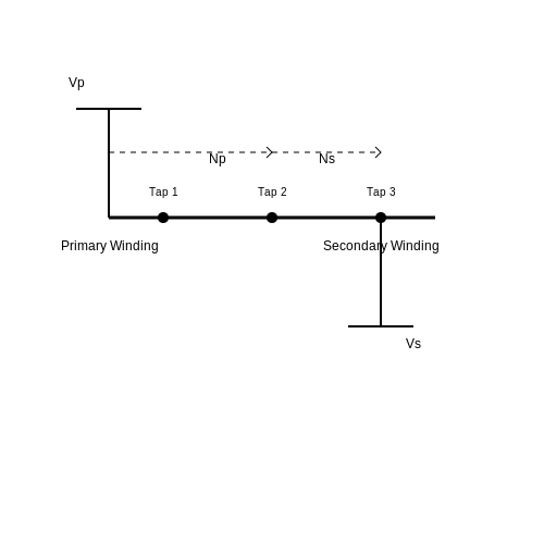
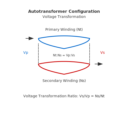
The winding structure of an autotransformer is critical to its function. The single winding is divided into two parts: the primary and the secondary, which are interconnected. This dual role allows for the adjustment of voltage levels without the need for separate windings. The voltage ratio of the transformer is determined by the ratio of the lengths of the common winding section over the total winding length.
Mathematically, this relationship can be expressed as:
Where:
- Vs = Secondary voltage
- Vp = Primary voltage
- Ns = Number of turns in the secondary winding
- Nt = Total number of turns in the winding
This equation highlights the operational principle underlying voltage transformation in autotransformers. The approach leads to a lightweight and compact design, making autotransformers particularly attractive for applications needing space-saving solutions.
Insulation Considerations
Due to their unique winding structure, insulation plays a crucial role in the safety and performance of autotransformers. Insulation must be applied strategically to protect the winding sections from electrical breakdown. In practice, materials such as polyester films or ceramic composites are often employed to ensure reliability under variable operating conditions. Insulation barriers must withstand not only the operational voltage but also potential transients during normal operation, which may arise from load variations.
Efficiency and Losses
One of the significant advantages of autotransformers is their enhanced efficiency compared to conventional transformers. Since they utilize less copper and iron, they exhibit lower losses. However, core losses (hysteresis and eddy current losses) and copper losses still demand attention. Effective design strategies include optimizing the winding arrangement and core sizing to minimize these losses under specific operating loads.
In practical applications, autotransformers find usages ranging from voltage regulation in power distribution systems to power supplies interfacing with sensitive electronic equipment. Their ability to efficiently manage voltage levels while conserving space and material makes them a preferred choice in various engineering applications.
Conclusion
In summary, the construction and design features of applied autotransformers reflect a finely tuned balance among efficiency, material usage, and operational reliability. Understanding these features enables engineers and physicists to optimize autotransformers for specific applications while also addressing challenges related to insulation and losses. As technology continues to evolve, advancements in materials and design methodologies will undoubtedly enhance the performance and applicability of autotransformers further.
2. Voltage Regulation Mechanisms
2.1 Voltage Regulation Mechanisms
Applied autotransformers serve a pivotal role in voltage regulation, utilizing their unique configuration to adapt voltage levels efficiently. Understanding the mechanisms behind voltage regulation is crucial for engineers and researchers, as these principles directly influence system stability and performance. At the core of autotransformer operation is the manipulation of voltage ratios through its winding design.
Fundamental Principles of Voltage Regulation
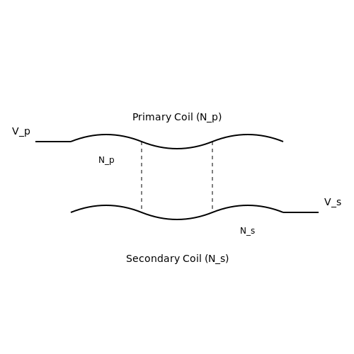
In a typical autotransformer, the primary coil is electrically connected to the secondary coil, allowing for the direct transfer of energy while permitting different voltage levels. The key to its operation lies in the turns ratio, which governs the relationship between primary and secondary voltages. If we designate the number of turns in the primary winding as \(N_p\) and that in the secondary as \(N_s\), the output voltage \(V_s\) can be derived from:
Where \(V_p\) represents the input voltage. This formula succinctly illustrates how altering the turns ratio can provide desired voltage outputs, thus enabling effective voltage regulation in various applications.
Dynamic Voltage Regulation Mechanisms
Voltage regulation in applied autotransformers can occur through several dynamic mechanisms. The fundamental method relies on the autotransformer's ability to adjust the turns ratio in real-time by utilizing an adjustable winding configuration or taps along the winding. This method permits voltage adjustments based on load conditions, maintaining output stability under varying input voltage levels.
Another crucial mechanism involves feedback control systems, where voltage is continuously monitored, and adjustments to the transformer configuration or the input supply are made accordingly. Such systems often employ electronic regulators or microcontrollers equipped with sensors, enhancing accuracy and response times in maintaining voltage levels.
Impact of Load Variation
The response of an autotransformer to fluctuating load conditions is a critical aspect of its voltage regulation capabilities. The load connected to the secondary side effectively influences the voltage drop due to the internal resistance of the transformer and the resistive components in the load circuit.
The voltage regulation percentage can be expressed mathematically as:
This equation quantifies the performance of an autotransformer under increased load, helping engineers assess efficiency and efficacy in practical applications.
Practical Applications of Voltage Regulation Mechanisms
Applied autotransformers are widely used in industrial applications where varying power demands are common. For instance, they are integral to systems requiring fine voltage adjustments, such as those in HVAC systems, which fluctuate based on environmental changes or operational demands. These transformers also find use in renewable energy systems, including wind and solar, where fluctuating power production necessitates robust voltage regulation measures to minimize energy losses and maintain grid stability.
In summary, the mechanisms behind voltage regulation in applied autotransformers are essential to ensuring reliable performance across several domains. As technology advances, ongoing research seeks to further enhance these mechanisms, including the integration of smart technologies that automate the regulation process and enhance adaptability in complex electrical networks.
2.2 Efficiency and Losses in Autotransformers
Autotransformers are renowned for their efficiency, particularly in applications involving voltage regulation and power distribution. Their design allows them to minimize losses compared to conventional transformers, primarily through the shared winding arrangement. However, understanding the factors that contribute to inefficiencies is paramount for optimizing their performance in practical situations.
Understanding Efficiency in Autotransformers
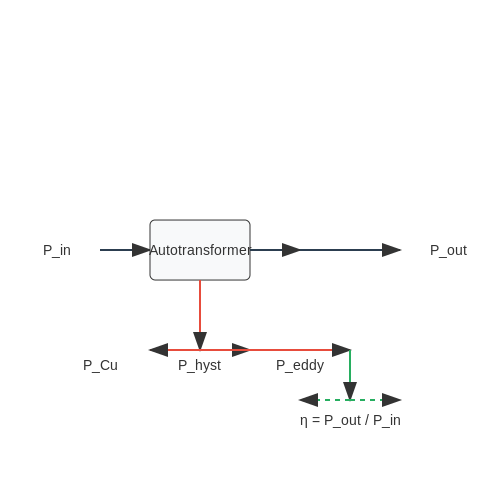
The efficiency of an autotransformer can be defined as the ratio of useful output power to the input power. Mathematically, it can be expressed as:
Where:
- Pout: Power delivered to the load.
- Pin: Power supplied from the source.
High efficiency is crucial in applications where energy loss translates directly into increased operational costs. Autotransformers can achieve efficiencies exceeding 95% under optimal conditions, which is significantly higher than their two-winding counterparts.
Sources of Losses in Autotransformers
Even with their high efficiency, autotransformers do incur certain types of losses that are important to consider:
Copper Losses
Copper losses occur due to the inherent resistance in the winding conductors. These losses can be accounted for by:
Where:
- PCu: Cut copper loss.
- I: Current flowing through the winding.
- R: Resistance of the winding coils.
To minimize copper losses, one must optimize the winding material (using higher conductivity materials) and reduce the resistive path by designing thicker wires.
Core Losses
Core losses, also known as iron losses, consist of two main components: hysteresis losses and eddy current losses. Hysteresis losses arise from the magnetic properties of the core material and can be quantified by:
Where:
- Physt: Hysteresis loss.
- k, n, m: Material-specific constants.
- f: Frequency of the alternating magnetic field.
- Bmax: Maximum magnetic flux density.
Eddy currents are circulating currents induced within the core itself due to the changing magnetic field. Reducing eddy current losses involves using laminated core designs with insulation between layers or employing core materials with high electrical resistivity.
Real-World Implications of Efficiency
In practical implementations, the choice of materials and design concepts directly influences the operational efficiency of autotransformers. For example, in electrical substations, where autotransformers are commonly used for voltage adjustments, higher efficiency contributes to lower operational costs and improved sustainability.
Furthermore, efficiency gains can lead to extended equipment lifespan, enhanced reliability, and reduced electromagnetic interference (EMI)—a critical consideration in densely populated electrical environments.
As the push for energy-efficient designs continues in various industries, understanding and minimizing losses in autotransformers becomes increasingly important in meeting both economic and environmental goals.
Summary
In summary, while autotransformers are inherently more efficient than traditional transformers, they are not without their limitations. The focus on minimizing copper and core losses through appropriate material selection and design optimization can enhance their performance significantly, ensuring that these devices contribute effectively to energy efficiency strategies in modern electrical systems.
2.3 Short-Circuit and Open-Circuit Conditions
Understanding the operational states of applied autotransformers, particularly during short-circuit and open-circuit conditions, is crucial for both safety and functional applications. These conditions can significantly influence the performance metrics of the transformer, including voltage regulation, efficiency, and stability. Proper analysis not only ensures adherence to safety protocols but also enhances the reliability of electrical systems.
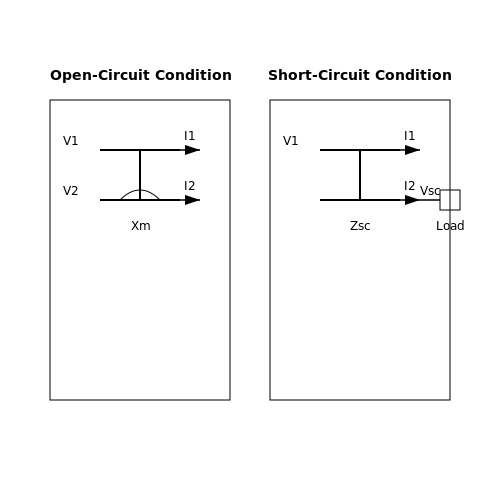
Open-Circuit Condition
Under open-circuit conditions, the secondary winding of the autotransformer is disconnected from any load. This condition allows for the measurement of the no-load voltage across the secondary terminals, which is critical for assessing the transformer's voltage regulations and efficiency. In theory, the primary voltage appears across the secondary winding without any load impedance.
To analyze the open-circuit condition, we can represent the autotransformer in its equivalent circuit. The key parameters include:
- Primary Voltage (V1): The input voltage applied to the primary winding.
- Secondary Voltage (V2): The voltage across the secondary terminals under no load.
- Primary Current (I1): Currents in the primary winding, primarily constituting the magnetizing current.
- Magnetizing Reactance (Xm): Represents the reactance due to magnetization of the core.
The primary current can be approximated as:
The secondary voltage in open circuit can be calculated as follows:
Where N1 and N2 are the turns of the primary and secondary windings, respectively. In this configuration, the autotransformer demonstrates maximum efficiency because there is no load reduction of voltage due to current flow.
Short-Circuit Condition
Conversely, a short-circuit condition occurs when the secondary winding is fully engaged with a load offering negligible impedance, essentially causing a direct short across the terminals. This scenario is critical for determining the short-circuit current and understanding the transformer's thermal behavior under overload conditions.
The analysis of short-circuit conditions requires us to consider:
- Load Current (I2): The resultant current flowing through the secondary winding during a short circuit.
- Short-Circuit Voltage (Vsc): The voltage applied across the primary to produce a specific short-circuit current.
- Impedance (Zsc): The short-circuit impedance, which is a measure of the total opposition to current flow.
We can express the short-circuit current using Ohm’s Law as:
The short-circuit voltage can also be expressed with respect to the primary voltage:
This condition serves as a significant indicator of the autotransformer's performance, helping engineers gauge how the transformer will behave under fault conditions. An uncompensated rise in current can lead to overheating, damaging the transformer and connected systems.
Practical Relevance
In practical applications, understanding these conditions is vital for system design and safety. Autotransformers are widely utilized in applications such as:
- Voltage Regulation: Efficiently adjusting voltage levels in renewable energy systems and power distribution networks.
- Start-up and Control: Providing necessary voltage boosts for motor control in industrial applications.
- Load Testing: Assisting in the assessment of equipment's thermal limits during tests to ensure compliance with operational specifications.
Comprehending the implications of both the short-circuit and open-circuit conditions enhances engineers' capabilities in effectively utilizing autotransformers in their designs while protecting against potential operational hazards.
3. Autotransformers in Power Distribution
3.1 Autotransformers in Power Distribution
Autotransformers serve as vital components in modern power distribution systems. Their unique design, featuring a single winding functioning as both primary and secondary, affords them several advantages over traditional transformers, particularly in applications where voltage adjustment is necessary. This section delves into the operational principles and practical applications of autotransformers in power distribution, highlighting their pivotal role in enhancing energy efficiency and reliability.
Operating Principles of Autotransformers
The operational mechanism of an autotransformer is rooted in electromagnetic induction, similar to conventional transformers. However, the design enables a portion of the winding to serve dual purposes. This configuration allows for a significantly reduced size and weight compared to conventional transformers, making them particularly attractive for power distribution applications.
To understand their functionality, consider the voltage transformation ratio, which is defined by the turns ratio between the primary and secondary sides. An autotransformer can step up or step down voltage based on the connection configuration of the winding.
In terms of voltage transformation, the relationship can be expressed mathematically as follows:
Where:
- V_s = secondary voltage
- V_p = primary voltage
- N_s = number of turns in the secondary section
- N_t = total number of turns
This relationship showcases the autotransformer's ability to convert voltage levels efficiently with reduced energy losses.
Applications in Power Distribution
Autotransformers are extensively utilized in various facets of power distribution, primarily in the following applications:
- Voltage Regulation: Autotransformers are commonly employed in voltage regulation systems within power substations. They maintain system voltage levels despite variations in load, ensuring reliability in power delivery.
- Connection with Rectifiers: In conjunction with rectifiers, autotransformers facilitate controlled DC power supply for industrial processes, enhancing operational efficiency.
- Starting Induction Motors: They play a critical role in the soft starting of large induction motors, reducing inrush current and minimizing mechanical stress.
- Interconnection between Voltage Levels: Autotransformers enable the interconnection of different voltage systems (e.g., 110 kV to 33 kV), reducing infrastructure costs while maintaining operational efficacy.
The versatility of autotransformers in these applications not only optimizes energy transmission but also contributes to system longevity and sustainability.
Case Studies
Several case studies illustrate the effective deployment of autotransformers in power distribution networks:
1. Urban Power Distribution Networks
In urban settings where space and weight are crucial considerations, utilities have successfully integrated autotransformers to convert and regulate voltage with minimal footprint. An analysis of the power distribution system in a metropolitan area in Europe demonstrated a reduction in transformer sizes by approximately 30%, leading to substantial savings in installation costs.
2. Industrial Applications
A manufacturing facility in Asia incorporated autotransformers for the soft starting of large motors used in heavy machinery. This implementation not only reduced initial startup current by nearly 50% but also extended the lifespan of the motors, thereby minimizing operational downtime and maintenance costs.
In summary, autotransformers prove their worth in power distribution by offering enhanced efficiency, cost savings, and improved operational reliability. As electrical grids evolve towards more sustainable solutions, the role of these devices will only become more pronounced, uniting technological advancements with practical implementation. Their understanding lays the groundwork for future innovations in electrical engineering and energy distribution systems.
3.2 Use in Motor Starting Applications
In the realm of electrical engineering, the ability to start large induction motors efficiently and safely is a critical concern. Applied autotransformers serve as a versatile solution, enabling reduced starting currents and controlling voltage levels while providing the necessary torque to initiate motor operation. These transformers capitalize on the principle of voltage transformation, offering a configuration that allows for a more economical use of copper and iron compared to traditional transformers.Principle of Operation
An autotransformer consists of a single winding that acts in two ways: as the primary side and as a tap for the secondary side. The voltage level achieved at the motor's terminals is adjustable, depending on the number of turns utilized. This approach benefits from both reduced cost and weight compared to two-winding transformers. The autotransformer operates based on the principle of electromagnetic induction, utilizing the following equation for the turns ratio:Advantages of Autotransformers in Motor Starting
Utilizing applied autotransformers in motor starting applications offers several advantages:- Reduced inrush current: By lowering the starting voltage, the current drawn during startup is minimized, alleviating stress on electrical components.
- Compact design: Due to their single-winding configuration, autotransformers are generally smaller and lighter than conventional transformers, which is beneficial in space-constrained environments.
- Cost-effective: Reduced copper and iron usage translates to lower material costs, making autotransformers an economically attractive option for motor starting solutions.
Application Examples
In industrial environments, large motors used in pumps, conveyors, and compressors often require heavy starting currents. For instance, a 500 HP induction motor can draw up to six times its rated current at startup. By integrating an autotransformer, the starting voltage can be adjusted down to approximately 80% of the line voltage, significantly mitigating inrush current effects.Case Study: Water Treatment Facility
A case study on a water treatment facility revealed the effective use of an autotransformer to start large submersible pumps. The facility faced challenges with inrush currents affecting upstream equipment during normal operations. After installing an autotransformer, the facility reported a drop in starting currents by 50%, leading to smoother operations and reduced maintenance costs on electrical infrastructure.Conclusion
The integration of applied autotransformers in motor starting applications represents a practical solution to manage inrush currents effectively while maintaining operational efficiency. Through careful selection of voltage levels and turns ratios, engineers can optimize the starting process for electric motors across a diverse range of industries, enhancing reliability and reducing costs. As technology evolves, continued innovations in autotransformer applications will likely bring forth even more efficient designs and enhanced operational capabilities.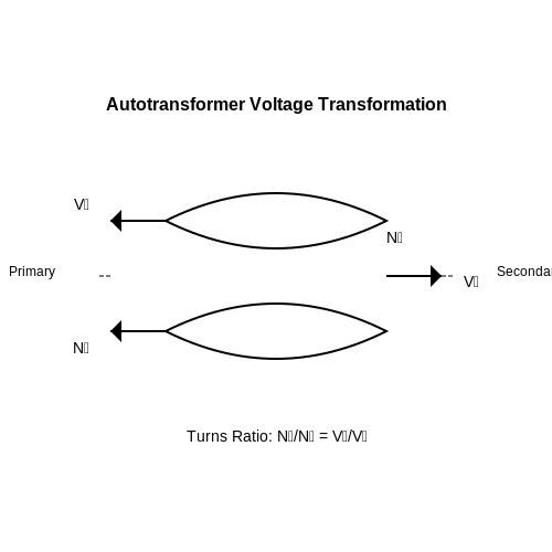
3.3 Autotransformers in Audio Equipment
Autotransformers, characterized by their single winding configuration that serves as both primary and secondary winding, offer unique benefits that are particularly relevant in audio applications. Their ability to step up or step down voltages with minimal energy loss makes them an attractive choice in diverse areas of audio equipment, from amplifiers to loudspeakers.
Functionality and Efficiency
The operational principle of autotransformers revolves around electromagnetic induction, similar to traditional transformers. However, the primary advantage is rooted in their efficiency. In an autotransformer, a greater portion of the input power can be transferred to the output due to the common winding. This results in lower copper losses, making them particularly advantageous in audio systems that demand high fidelity and low distortion.
Performance Versus Traditional Transformers
In audio applications, transformer performance is critically assessed by its impedance matching capability, linearity, and bandwidth. The single-winding structure of an autotransformer allows it to maintain better bandwidth and transient response than traditional two-winding transformers. This efficiency becomes particularly important in high-power audio systems where the signal integrity is paramount. In contrast to conventional transformers, which can introduce additional phase shifts and frequency dependent distortions, autotransformers provide a more linear response across a range of frequencies, resulting in clearer sound reproduction.
Applications in Audio Equipment
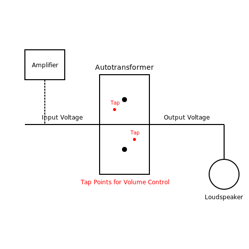
One of the most prevalent uses of autotransformers in audio equipment is within loudspeaker systems. They are often employed in matching the impedance of loudspeakers to amplifier outputs, greatly enhancing performance. Because they can be designed to accept a range of input voltages while maintaining a consistent output voltage, they allow previous generations of amplifiers to work with newer speaker technologies, extending their usability.
- Volume Control: Autotransformers serve effectively as volume controls in audio systems. By varying the tap point on the winding, audio engineers can adjust the audio signal levels without introducing notable distortion.
- Impedance Matching: Their ability to match impedances optimally between different audio components reduces power loss and enhances overall system efficiency.
- Crossover Networks: Autotransformers can be integrated into crossover networks within multi-driver speaker systems, ensuring each driver receives an appropriate frequency range, thus maintaining sound balance and clarity.
Historical Context and Development
The use of autotransformers in audio applications gained momentum in the mid-20th century, aligning with advancements in audio technology and recording equipment. The evolution from all-tube audio systems to modern transistor-based designs provided fertile ground for the integration of efficient transformer designs. As audio fidelity standards rose, the simplistic yet effective structure of autotransformers proved to be invaluable. Today, they continue to be utilized within high-end audio devices, reflecting a blend of innovative engineering and time-tested techniques.
Key Considerations
While autotransformers offer distinct advantages, their design must be approached carefully. For instance, the reduction in isolation between input and output can lead to potential issues such as ground loops. This makes proper grounding and shielding a critical aspect during circuit design. Furthermore, careful selection of materials and winding techniques can further enhance performance by minimizing unwanted inductive and capacitive couplings.
Overall, the application of autotransformers in audio equipment exemplifies the intersection of fundamental physics with practical engineering. By harnessing their unique properties, audio professionals can deliver high-quality auditory experiences that fulfill increasingly demanding consumer expectations.
4. Benefits Over Traditional Transformers
4.1 Benefits Over Traditional Transformers
In the realm of electrical engineering, the increasing demand for efficiency and compactness has led to the development and application of autotransformers. Their unique design diverges significantly from that of traditional transformers, offering a myriad of advantages that are particularly relevant in today’s technologically advanced landscape.
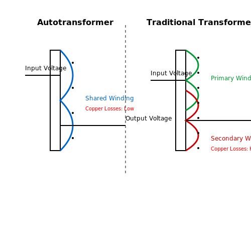
Efficiency and Reduced Energy Loss: Autotransformers exhibit inherently greater efficiency compared to their traditional counterparts. Since a portion of the winding is shared between the primary and secondary circuits, the copper losses are minimized. This design reduces the amount of wire required and thereby decreases the resistive losses, which can be significant in larger transformers.
Compactness and Weight: Traditional transformers necessitate two distinct windings (primary and secondary), which increases both their size and weight. In contrast, autotransformers utilize a single winding that serves both functions, leading to a more compact design. This reduction in size is particularly beneficial in applications with spatial constraints, such as embedded systems or mobile devices, where every millimeter counts.
Cost-Effectiveness: The simpler construction of autotransformers also translates into lower manufacturing costs. The reduction in materials required not only applies to copper wire; less insulation and core material are needed as well. This economic advantage is especially crucial in large-scale applications, such as commercial power distribution, where cost savings can impact overall project feasibility.
Versatility in Applications: Autotransformers can effortlessly cope with varying voltage levels, making them suitable for a vast array of applications, from small electronic devices to large transmission systems. Their ability to step down or up voltages efficiently allows for smooth voltage regulation, and this adaptability can enhance the performance of equipment across multiple industrial sectors, including telecommunications, automotive, and renewable energy systems.
Lower Stray Losses: Due to the shared winding structure, autotransformers can minimize stray losses that occur in traditional transformers. These losses often arise from the magnetic coupling associated with separate windings. By utilizing a single magnetic circuit, autotransformers can achieve better magnetic coupling, resulting in improved overall performance.
Despite these advantages, it's imperative to note that autotransformers also have certain limitations, such as the inability to provide electrical isolation between circuits, which may be critical in applications where safety is paramount. Nevertheless, the benefits discussed render autotransformers a compelling choice in various high-performance settings.
As the demand for smarter and more efficient electrical systems rises, the importance of understanding the advantages of autotransformers over traditional transformers becomes increasingly clear. Their advantages in terms of efficiency, size, and cost-effectiveness can play a significant role in advancing modern electrical engineering applications.
4.2 Limitations and Safety Concerns
Applied autotransformers are an essential component in electrical and power systems due to their efficiency and versatility. However, understanding their limitations and safety concerns is crucial for optimal utilization and risk management. This section provides an in-depth examination of these limitations, offering insights into how they impact practical application and system design.Understanding Limitations
One of the principal limitations of applied autotransformers is their inability to provide electrical isolation. Unlike traditional transformers, which have separate primary and secondary windings, an autotransformer has a single winding that serves both purposes. While this configuration enhances efficiency and reduces material costs, it simultaneously exposes users to higher electrical hazards in systems where isolation is critical. For instance, in applications such as power distribution and regeneration systems, electrical safety compliance mandates isolation to minimize the risk of electric shock. The absence of this feature in autotransformers can limit their use in certain industrial settings where personnel safety is paramount. Additionally, the voltage transformation ratio in autotransformers is less flexible than in conventional transformers. This rigidity can present challenges when scaling systems up or down or when precise voltage settings are required. Predominantly, autotransformers operate effectively within specific parameter ranges, and operating beyond these limits can lead to inefficiencies and potential overloads.Efficiency versus Losses
While autotransformers are generally known for their high efficiency, they are not free from losses. Core losses, primarily consisting of hysteresis and eddy current losses, occur due to alternating magnetic fields within the transformer core. The amount of loss depends on several factors, including core material, frequency, and design. The reduced copper losses found in autotransformers can often overshadow these core losses, but it is crucial to perform a comprehensive loss analysis when designing systems to ensure optimal performance. Engineers might often employ the following basic equation to evaluate the efficiency of autotransformers:Safety Concerns
In terms of safety, the lack of isolation can amplify the risk of faults leading to short circuits, whereas traditional transformers would typically prevent such occurrences via their isolated primary and secondary circuits. For autotransformers, fault conditions can create hazardous situations where high voltages may inadvertently reach the user or connected equipment. Moreover, overheating can arise from excessive loading beyond the transformer’s design limits. Operators must maintain vigilant monitoring for signs of thermal stress, which can manifest through temperature readings above the rated values. Implementing thermal protection devices, such as thermal overload relays, becomes imperative to mitigate risks associated with overheating. The material quality and design of autotransformers also play a role in determining thermal performance and the risk of fire hazards. The careful selection of insulating materials, optimal design standards, and regular maintenance checks can significantly reduce these risks. In applications where autotransformers are deployed in close proximity to highly sensitive electronic equipment, the potential for noise coupling must also be considered. Noise, arising from both load fluctuations and inherent transformer operation, can adversely affect the performance of sensitive devices. Engineers often use filtering techniques to mitigate these issues, improving the overall operational soundness of their systems. In summary, while autotransformers present numerous advantages, comprehending their limitations and safety concerns is fundamental for effective and responsible application. As engineers and technologists continue to innovate within this field, prioritizing safety while maximizing efficiency will remain a crucial challenge.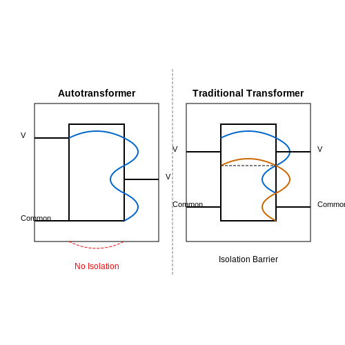
5. Hybrid Autotransformer Applications
5.1 Hybrid Autotransformer Applications
Introduction to Hybrid Autotransformers
Hybrid autotransformers, which combine features of traditional transformers and autotransformers, address peculiar challenges in electrical systems. Designed for enhanced efficiency and versatility, they find applications in various domains, ranging from power systems to industrial electronic circuits. Understanding the mechanics and their practical relevance elucidates their role in modern electrical engineering.The Principles of Operation
To appreciate the role of hybrid autotransformers in applications, one must first understand their operating principles. A hybrid autotransformer consists of both a common winding and a separate secondary winding, creating a configuration that retains key advantages of isolation while improving efficiency through low copper losses. This arrangement capitalizes on the principle of electromagnetic induction, where alternating current (AC) flowing through the primary winding produces a magnetic field that induces a voltage in the secondary winding. The connection of the secondary coil to the primary—typically involving a portion of the primary winding—reduces the amount of copper required compared to traditional step-down transformers. An equation for the voltage transformation ratio \( k \), which determines the relationship between the primary voltage \( V_p \) and the secondary voltage \( V_s \), is given by:Power and Efficiency Considerations
In hybrid autotransformers, power transmission efficiency is a crucial factor, especially in contexts where energy loss translates directly to operational costs. The efficiency \( \eta \) can be defined as:Applications in Power Distribution
One of the most prevalent applications of hybrid autotransformers is in power distribution networks. They effectively adjust voltage levels to match the requirements of users at varying distances from generation sources. The ability to step up or down voltage with minimal losses plays a critical role in long-distance transmission, where maintaining voltage levels is essential to reduce line losses and ensure reliable delivery. In this context, hybrid autotransformers also facilitate voltage regulation in substations, ensuring that end-users receive stable and efficient power. Their compact design makes them suitable for urban underground cable systems and renewable energy plants, where space is limited and operational efficiency is paramount.Industrial Uses
In industrial systems, hybrid autotransformers are employed in various applications, including:- Motor Starting Systems: These devices can stabilize the high starting currents experienced by large industrial motors, ensuring a gradual increase in torque and less mechanical stress.
- Voltage Stabilization: By integrating hybrid autotransformers within automation systems, industries can maintain consistent voltage levels across processes, resulting in reduced downtimes.
- Load Balancing: Hybrid autotransformers assist in distributing loads evenly across three-phase systems, enhancing system longevity and efficiency.
Conclusion
Hybrid autotransformers represent a significant advancement in transformer technology, yielding versatility and efficiency across numerous applications. Their functional principles enable engineers to tackle pressing challenges in the ever-evolving electrical landscape, making them invaluable components in modern power systems and industrial applications. As the demand for efficient energy solutions continues to grow, the role of hybrid autotransformers will likely expand, leading to new and innovative uses.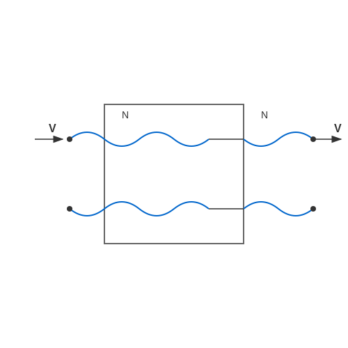
5.2 Modern Developments in Autotransformer Technology
The field of autotransformer technology has seen significant advancements in recent years, driven by the increasing demand for efficient, compact, and reliable electrical solutions. As a type of transformer that shares common windings for both primary and secondary circuits, autotransformers are recognized for their built-in efficiency advantages as well as versatility in applications such as power distribution, voltage regulation, and impedance matching. Through continuous innovations, modern autotransformers have developed features that cater to the evolving needs of industrial automation, renewable energy integration, and electric vehicle (EV) technology. Some of the most noteworthy changes include enhanced materials, dynamic control techniques, and intelligent monitoring systems.Material Advancements
With ongoing research into new materials, the performance characteristics of autotransformers have improved significantly. For example:- High-Temperature Superconductors (HTS): The application of HTS materials can drastically reduce resistive losses. Due to their ability to operate at cryogenic temperatures, these materials can support substantial current loads while maintaining minimal energy loss.
- Amorphous Steel: Utilizing amorphous steel in core construction lessens core losses, particularly at higher frequencies. This advancement is especially useful in transformer applications requiring compact designs.
Dynamic Control Techniques
Dynamic control techniques, particularly those employing digital signal processors (DSPs) and microcontrollers, have transformed traditional approaches to managing autotransformer performance. Some examples include:- Phase-Shifting Control: This technique varies the phase angle of the supply voltage to control output voltage without the need for mechanical tap changers. It enables rapid adjustments, leading to better voltage regulation in real-time conditions.
- Smart Grids and Communication Protocols: Modern autotransformers can be integrated into smart grid systems, allowing for two-way communication for load management, predictive maintenance, and remote operation. Protocols such as DNP3 and IEC 61850 aid this integration.
Intelligent Monitoring Systems
The advent of IoT technologies has introduced the concept of intelligent monitoring systems that enhance the reliability and safety of autotransformers. These systems typically feature:- Condition Monitoring: Sensors monitor parameters such as temperature, load, and voltage levels. By applying predictive analytics, potential failures can be identified before they occur, reducing downtime.
- Integrated Diagnostics: Diagnostic modules that provide real-time data on performance and health can alert operators to abnormal conditions, enabling timely interventions.
Real-World Applications
The modern advancements in autotransformer technology are reflected in various real-world applications. For instance, in renewable energy setups like wind and solar farms, autotransformers efficiently manage output voltage to match grid requirements while minimizing losses. Similarly, in urban settings where electric vehicle charging stations are proliferating, smart autotransformers can adjust voltage levels automatically, ensuring optimal charging efficiency and speed. In summary, the continuous evolution of autotransformers through material science, dynamic control techniques, and intelligent monitoring systems underscores their importance in contemporary electrical engineering practices. These advancements not only improve efficiency and reliability but also pave the way for embracing sustainable energy solutions.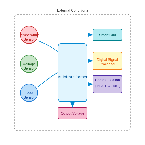
6. Recommended Books on Autotransformers
6.1 Recommended Books on Autotransformers
- Autotransformers and Vernier Transformers: Electrification Issues — A comprehensive book offering insight into the applications of autotransformers in various electrification projects. It covers practical issues, advanced design techniques, and historical case studies, making it a valuable resource for engineers and researchers.
- Transformer Engineering: Design and Practice, 2nd Edition — This book provides a detailed exploration of transformer technology, including autotransformers. Readers will find extensive coverage on theory, practical design, and maintenance, with modern updates aligning with today's electrical systems.
- Electrical Power System Essentials — This text introduces essential concepts surrounding power systems, emphasizing the role of autotransformers in transmission and distribution. It's particularly useful for those seeking a clear understanding of how autotransformers integrate into broader electrical networks.
- Power Transformer Handbook — Packed with real-world examples, this handbook offers a thorough examination of power transformers, including specialized sections on autotransformers. It is rich with conceptual diagrams and practical approaches for advanced students and industry professionals.
- Transformer Design: Principles and Techniques — A scholarly article focused on the principles of transformer design, with an emphasis on autotransformers' role in various system configurations. The paper's technical depth makes it suitable for advanced readers looking for scholarly insights.
- Generalized Theory of Automated Transformer Design — This book delves into the automated design process of transformers, including autotransformers, highlighting software tools and algorithmic methods for streamlined design solutions.
- Electric Power Systems: Advanced Power System Analysis and Design — Offering a comprehensive view on electric power systems, this book includes chapters on the application and design of autotransformers, focusing on their role in enhancing system performance and reliability.
6.2 Relevant Journals and Articles
- IEEE Journals on Transformers — This IEEE portal provides access to numerous studies and articles on transformers, including detailed analyses and advancements in autotransformer applications.
- ScienceDirect: Autotransformer Topics — Explore a variety of documents and papers on ScienceDirect that cover technical aspects and research findings related to autotransformers.
- ResearchGate: Advancements in Autotransformer Technology — A comprehensive article on ResearchGate discussing the latest technological advancements and practical implementations of autotransformers in electrical systems.
- SAGE Journals: Autotransformers in Electrical Engineering — This article examines the role of autotransformers in the field of electrical engineering, focusing on design innovations and efficiency improvements.
- IET Digital Library: Transformer Developments — Offers insights into the latest research and developments in transformer technologies, highlighting advances in autotransformers for grid applications.
- SpringerLink: Optimization Techniques for Autotransformers — An in-depth paper discussing optimization techniques used to enhance the performance and reliability of autotransformers.
- MDPI Energies: Special Issue on Autotransformers — A special issue of the MDPI Energies journal focusing on the environmental and economic impacts of using autotransformers in modern power systems.
6.3 Online Resources and Communities
For advanced learners, engineers, researchers, and graduate students seeking to delve deeper into the realm of applied autotransformers, a wealth of resources and active communities are available online. These platforms offer opportunities for continuous learning, discussion, and sharing insights with fellow experts in the field. Below is a curated list of valuable online resources and communities that can enhance your understanding of applied autotransformers and related topics:
- ResearchGate — A significant academic networking site where researchers publish their work, engage in discussions, and keep up with new advances in areas such as power electronics and applied autotransformers.
- IEEE Publications — Offers access to a wide range of journals and conference papers, particularly IEEE Transactions on Power Electronics, which frequently feature applied research in autotransformers.
- EDAboard — A comprehensive community forum for electronics enthusiasts and professionals to discuss a variety of topics, including power transformer design and applications.
- Electronic Design - Power Management — Offers articles, news, and technical papers focused on power electronics, providing readers with in-depth insights into current trends and applications of auto-transformers.
- Electrical4U — A comprehensive educational platform offering tutorials and technical insights, including a focus on transformers and their application in electrical engineering.
- Quora - Transformers — A place where engineers and students can ask questions and get answers on various transformer-related topics from knowledgeable community members.
- LinkedIn Group on Power Transform Programs — Joins a professional network to connect with peers interested in the latest developments and discussions in power and autotransformers.
Engagement with these resources will allow readers to expand their knowledge, connect with experts, and stay updated on the latest advancements in the field of applied autotransformers.