



Voltage comparator amplifier circuit
Addition and subtraction of the operational amplifier through an external amplifier feedback network enables integrated operational amplifier in a deep state of...
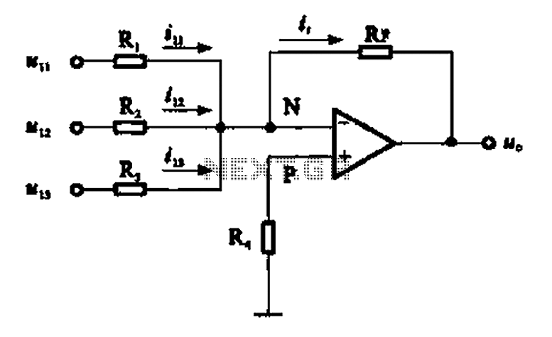
Adder circuit
Adder circuit commonly used inverting input, namely the inverting adder circuit. It was to the inverting input of the operational amplifier electrical path, bas...

Multiplicative -DA converter electronic attenuator
AD7s23 is an 8-bit multiplication DA converter, the output voltage of the analog input and the digital input of the product. Inside! Unit consists of eight anal...

CCD analog output signal processing circuit diagrams
AD623 integrated 3-way amplifier. Single or dual supply can work with high CMRR and low voltage drift, programmable gain control in addition to an external resi...

Functional Block Diagram for AD524 pin and internal circuit
AD524 low-drift (drift voltage 0.5mV, maximum drift 25 mV door C), low noise (0.3mVp p, 0.1-10Hz), good linearity ( 0.0030/0, a gain of l), high CMRR (120dB) ga...

AD524 differential shielded drive
AD524 differential shielded drive as shown in Fig. AD524 The RC:, RCz not only gain setting foot, also output feedback (internal 20kfl resistance) circuit part ...

LF356 composed of AD converter
A/D converter is the analog signal into a digital circuit, it has a variety of circuits, as shown in Figures 21-24 is a circuit A/D converter structure, which i...

Trap MC33171
A chopper circuit shown in FIG. The circuit uses a high-performance op amp device MC33171 constitute trap. The device has a wide band and a high conversion rate...
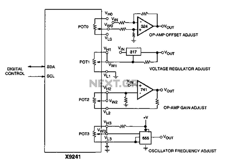
Corrector circuit diagram of an analog circuit
A XICOR X9241 POT IC module can be used to adjust the four digital analog circuits, as shown in the schematic. ...

Battery status indicator circuit diagram
741 op amp can be used as a voltage comparator. Non-inverting input and a zener control source. The reference voltage is 5.1V. R2 can adjust the in-phase input ...

Using the same parameters more convenient level 36dB-oct low-pass filter design
36dB/ocf Butterworth filter consists of three sub-ruined structure, each stage box with two filter sections c work zdB/ocf), in order to point a 3dB frequency c...
Using the same parameters more convenient level 36dB-oct low-pass filter design
36dB/ocf Butterworth filter consists of three sub-ruined structure, each stage box with two filter sections c work zdB/ocf), in order to point a 3dB frequency c...

The same capacitance parameters easy to change the cutoff frequency of the low pass filter 24dB-oct
24dB/oc seven times Butterworth (maximally flat characteristic) constituted by the two filters, each box has two books enough filter (12dB/oct), in order to mak...
The same capacitance parameters easy to change the cutoff frequency of the low pass filter 24dB-oct
24dB/oc seven times Butterworth (maximally flat characteristic) constituted by the two filters, each box has two books enough filter (12dB/oct), in order to mak...

12dB-oct by the OP amplifiers low-pass filter
12dB/oct Butterworth second port (most flat characteristic) of the filter circuit value is pregnant shall be 0.707 to get the characteristic flat, and for cl, t...

Active bandpass filter principle
Second order band-pass filter performance depends primarily on the quality factor Q and center frequency Si. In order to adjust the Q and. t a general first adj...

High-speed integrator circuit (LM101A, LM108)
As shown for the high-speed integrating circuit. The integration time constant circuit RtCt have a greater range. If you do not consider integrating capacitor C...

TDA6103Q having a feedback factor of the test circuit
As shown in FIG TDA6103Q test circuit with feedback factor is 1/150. Input signal Vi1, Vi2, Vi3 through the input resistor network consists of capacitors into t...

Active low-pass filter LM102 schematic
Shown for the active low pass filter circuit. Cut-off frequency fc of the circuit = 10kHz. Circuit, R1 and R2 ratio and the ratio of C1 and C2 can be various va...
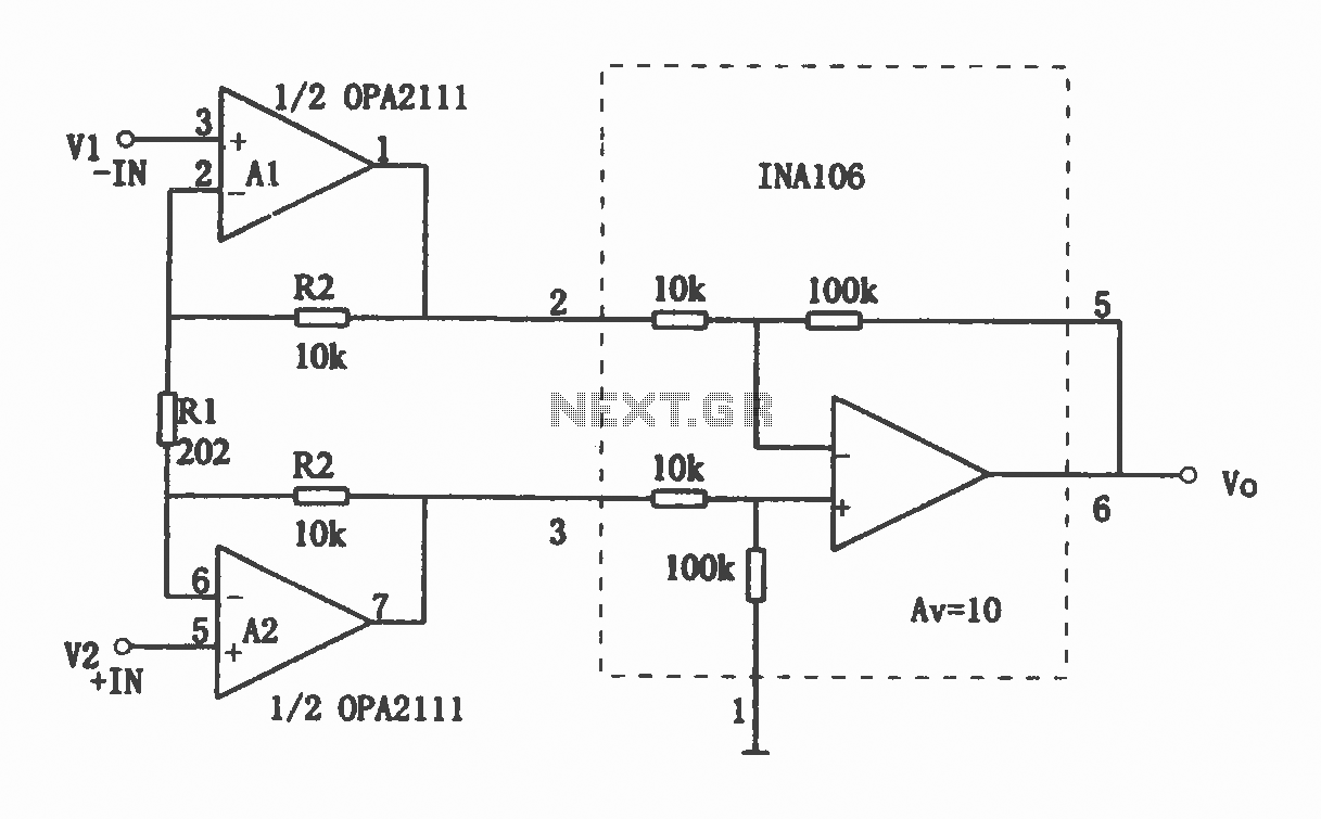
High-precision high-impedance instrument OPA2111 amplifier circuit
Shown for the high-precision, high-impedance instrument OPA2111 amplifier configuration. Total voltage circuit illustrated magnification Av = 10 (1 + 2R2 / R1) ...