Counters
1. Asynchronous Counters
1.1 Asynchronous Counters
Asynchronous counters, also known as ripple counters, are fundamental digital circuits that can count in binary without the need for a global clock signal. Instead, these counters rely on the propagation of signals from one flip-flop to the next, which leads to a ripple effect, hence the name. Understanding asynchronous counters is crucial for engineers and students as they serve as building blocks for various counting applications, frequency dividers, and digital systems.
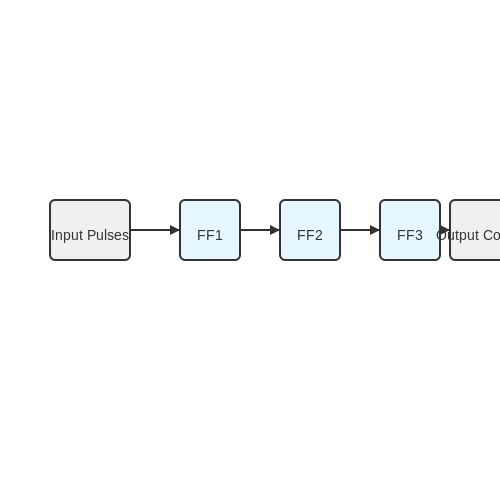
The primary components of an asynchronous counter include a series of flip-flops arranged in cascade, with the output of one flip-flop serving as the clock input for the next flip-flop in the sequence. Typically, JK flip-flops are used due to their versatility, but T flip-flops can also be employed to simplify the design.
Operation of Asynchronous Counters
To grasp the functionality of asynchronous counters, let's examine the basic principle behind their operation. Consider a two-bit binary counter constructed from two JK flip-flops:
- The first flip-flop (FF1) toggles its state with each clock pulse.
- The output Q1 from FF1 serves as the clock input for the second flip-flop (FF2).
- Thus, FF2 toggles its state on the falling edge of Q1.
- As a result, the output is divided by 2 at each flip-flop, leading to a binary counting sequence.
This mechanism introduces a timing delay as the signal propagates from FF1 to FF2, resulting in a characteristic ripple effect. This ripple can cause glitches in high-frequency applications and may limit the maximum speed at which the counter can reliably operate.
Timing Diagrams and Glitches
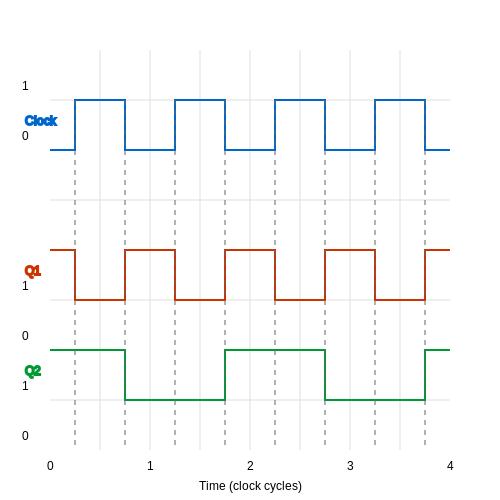
The timing diagram of a 2-bit asynchronous counter offers an insightful perspective into its operation. Initially, both flip-flops are reset to 0. As clock pulses are applied, the state transitions can be observed:
- On the first clock pulse, FF1 toggles to 1, and FF2 remains at 0.
- On the second clock pulse, FF1 toggles back to 0, while FF2 toggles to 1, producing the binary value 10.
- Following this sequence, the outputs evolve to produce 00, 01, 10, and finally 11.
This progression results in a count sequence of 0 to 3 (00 to 11 in binary). However, timing discrepancies can lead to glitches where both Flip-Flops appear to change states nearly simultaneously during transitions, particularly at high frequencies. Proper design considerations must be taken to mitigate these issues, especially in critical applications.
Applications of Asynchronous Counters
Despite their limitations, asynchronous counters find valuable applications in various fields:
- Frequency Division: They serve as efficient frequency dividers in clock generation circuits.
- Event Counters: Used in electronic devices to count occurrences, such as in digital clocks and event recording systems.
- Memory Addressing: Assisting in addressing different memory locations in computer systems.
In summary, asynchronous counters exemplify a simple yet effective method of counting in digital circuits. Their propagation delay should be accounted for during design and implementation to ensure reliability and performance.
Further exploration and practical implementation of these counters can be conducted through simulation software, such as Multisim or Logisim, which allows for hands-on experience in designing and troubleshooting asynchronous counters.
Where \(f_{out}\) is the output frequency, \(f_{in}\) is the input frequency, and \(n\) is the number of flip-flops used.
Conclusion
Asynchronous counters, with their ripple effect and unique counting mechanism, remain a staple in digital electronics. Their fundamental characteristics and practical applications showcase the balance between simplicity and functionality in circuit design.
In the next section, we will delve into synchronous counters, which address the propagation delay challenges faced by asynchronous designs. Understanding these distinctions will further enhance your proficiency in counter technologies.
1.2 Synchronous Counters
Synchronous counters represent a fascinating subset of digital counters, distinct in their operation and design principles from asynchronous counters. A synchronous counter uses clock signals to coordinate the transitions of all its flip-flops simultaneously, enhancing timing accuracy and reducing propagation delays—a common issue with asynchronous designs. At the heart of a synchronous counter's operation lies the use of flip-flops—typically D or JK types—which are triggered by a shared clock pulse. When the clock signal transitions, all flip-flops experience synchronous state changes based on their inputs. This setup allows for precise controlled counting sequences, ideal for applications requiring reliable timing signals.Design Principles
To understand the workings of synchronous counters, it is essential to appreciate the role of a clock signal as a timing reference. Unlike asynchronous counters where flip-flops can trigger each other in a ripple effect, synchronous counters employ a unified clock signal. This design minimizes the risk of inconsistencies that may arise from propagation delays during clock transitions. Moreover, a synchronous counter consists of a cascading arrangement of flip-flops each capable of storing a single bit. For an n-bit synchronous counter, n flip-flops are linked such that the output of the first flip-flop acts as the least significant bit (LSB), while the last flip-flop serves as the most significant bit (MSB). The counter's output sequence adheres to binary counting rules, ranging from 0 to \(2^n - 1\).Operation and State Transition
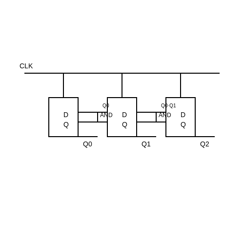
Let’s delve into the operation of a simple 3-bit synchronous binary counter. The synchronous counting operation can be represented by the flip-flops' state transitions. For three flip-flops, the counter will count from 000 to 111 in binary, which corresponds to decimal values from 0 to 7. To derive state transitions mathematically, we can formulate the next state logic for a binary counter. For each flip-flop \(Q_i\): - Flip-flop 0 (LSB) toggles with every clock pulse: $$ Q_{0, next} = \overline{Q_0} $$ - Flip-flop 1 toggles when Flip-flop 0 transitions from 1 to 0: $$ Q_{1, next} = Q_1 \oplus Q_0 $$ - Flip-flop 2 toggles when both Flip-flop 0 and 1 transition from 1 to 0: $$ Q_{2, next} = Q_2 \oplus (Q_1 \land Q_0) $$ Here, we utilize logic gates to implement the required conditions (AND, OR, XOR). The final equations for each flip-flop are critical for designing the input logic that drives the flip-flops based on the current states.Applications and Practical Relevance
Synchronous counters are not just theoretical constructs; they find extensive application in various domains. They are utilized in digital clocks, frequency counters, binary search algorithms in digital systems, and even programmable logic controllers (PLCs). The precise control offered by synchronous counters makes them ideal for systems where timing and synchronization are paramount. Particularly, they are essential in designing complex digital systems where multiple states must be efficiently managed. In microcontrollers and digital signal processors (DSPs), synchronous counters support operations like event counting, timestamping, and state management in finite state machines (FSMs). Incorporating these principles yields robust and reliable digital systems characterized by reduced timing uncertainties, thus ensuring that your design functions correctly under varying operating conditions. The depth of knowledge regarding synchronous counters and their design principles is instrumental for engineers and researchers looking to innovate in the rapidly evolving domain of digital electronics.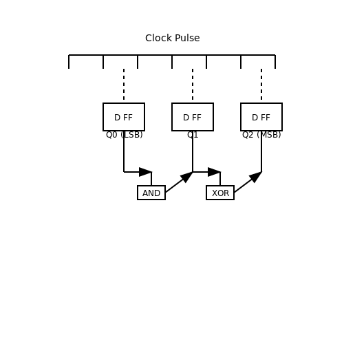
1.3 Up Counters
Up counters serve a fundamental role in digital electronics, functioning as a crucial component in a variety of applications ranging from simple digital clocks to complex event counters used in computer systems. An up counter counts sequentially in a binary format, increasing its value by one for each triggering event. Understanding the operation, design, and applications of up counters can lead to significant advancements in both theoretical and practical aspects of engineering.
Basic Operation of Up Counters
An up counter operates based on clock pulses that trigger its count sequence. With each pulse, the counter increments its current value by one. The simplest form of an up counter is a binary counter, which utilizes flip-flops to store and represent each bit of the count. For example, a 3-bit binary up counter can represent counts from 0 (000) to 7 (111), yielding a total of 8 distinct states.
The progression of these counts can be illustrated as follows:
- 0 (000)
- 1 (001)
- 2 (010)
- 3 (011)
- 4 (100)
- 5 (101)
- 6 (110)
- 7 (111)
At its core, the design of a binary up counter prominently uses D or JK flip-flops in its configuration. Each flip-flop corresponds to one bit of the counter. The synchronous nature of these components ensures that all flip-flops receive the clock signal simultaneously, enabling precise counting. Each flip-flop toggles its state based on the preceding flip-flop's state and the clock signal.
Design Considerations
When designing an up counter, several key considerations must be addressed:
- Number of Bits: The required range dictates the number of flip-flops to be employed. For example, an n-bit counter can count from 0 to \( 2^n - 1 \).
- Race Conditions: In asynchronous counters, glitches may occur due to varying propagation delays of flip-flops. This can be mitigated through synchronous designs.
- Speed and Frequency: The maximum clock frequency is essential to ensure reliable operation; it must be compatible with the flip-flops' switching times.
State Transition Diagram
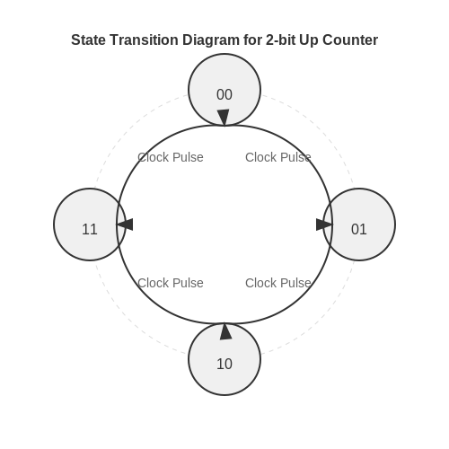
To visually interpret the functioning of a 2-bit up counter, we can utilize a state transition diagram. In this diagram, each state corresponds to a unique binary representation, and arrows indicate the transition from one state to the next with each clock pulse.
The diagram would depict a circular counter representing each state, transitioning back to the start after reaching the maximum count. This visual representation not only simplifies understanding but also aids in debugging and analysis during circuit design.
Real-World Applications
Up counters find significant applications across various fields:
- Digital Clocks: Used to count seconds, minutes, and hours efficiently.
- Event Counters: In industrial settings, to count the number of occurrences of a particular event, such as production counts or paged memory accesses in computers.
- Frequency Dividers: In signal processing, counters can be employed to divide the frequency of incoming clock signals, fundamental in creating lower frequency outputs.
- Frequency Synthesizers: Serve critical roles within radio and communication systems for generating various frequencies.
In conclusion, up counters are an essential building block in digital systems, beneficial for maintaining accurate counts in both simple and intricate applications. As technologies evolve, understanding the operational principles of these counters is paramount for engineers and researchers looking to innovate within the realms of electronics and computer science.
1.4 Down Counters
Down counters, often encountered in digital electronics, serve a fundamental role in counting applications. Unlike up counters, which increment a count on each clock pulse, down counters decrement the count. This section elucidates the architecture, operational principles, and applications of down counters, utilizing both theoretical foundations and practical examples.
Understanding Down Counters
A down counter is a sequential circuit that reduces its stored value with each clock cycle. The most fundamental type of down counter is the binary down counter, which counts in binary from a predetermined value to zero. For instance, a 4-bit down counter will count down from 15 (1111 in binary) to 0 (0000), with each clock pulse causing it to decrement by one.
The basic operation can be schematically represented as:
Where \( Q_{n} \) is the current state of the counter and \( Q_{n-1} \) is the previous state. The transition from one state to another is synchronous and relies on a clock signal.
Architecture of Down Counters
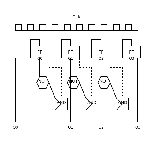
Typically, down counters can be implemented using flip-flops or counters integrated into programmable logic devices. For simplicity, we consider a 4-bit binary down counter implemented using a series of 4 flip-flops. The output of each flip-flop represents a bit of the stored count.
The transition between states in down counting is managed using combinational logic that generates the appropriate signals to toggle the flip-flops accordingly. The counter decrements using a combination of AND and NOT gates, which determine the control signals responsible for state changes.
Example: 4-Bit Down Counter Logic
For a 4-bit down counter implementing the logic, when the counter reaches the binary value of 0000, further clock pulses will cycle the output back to 1111, as a down counter wraps around. The truth table for such a down counter showcases the relation between input clock pulses and the flip-flop output states.
Applications of Down Counters
Down counters are extensively utilized in various applications across electronics. Here are some significant examples:
- Time Management Systems: In digital watches and timers, down counters serve to limit time intervals, ensuring countdown functionality.
- Frequency Division: Down counters can be used in frequency division applications, where the input signal needs to be reduced to a certain frequency by decrementing the count.
- Digital Sampling: In digital signal processing (DSP), down counters are often employed to extract segments of data samples or to synchronize data reads.
Ultimately, understanding the functionality and design of down counters enhances the engineer's ability to innovate within digital systems, yielding efficient designs for counting and timing applications.
1.5 Up/Down Counters
Up/down counters are a sophisticated variation of standard binary counters that can increment or decrement their count based on a control signal. These devices are critical in various applications such as digital clocks, frequency counters, and electronic voting systems, where the capability to count in both directions adds versatility to data collection and processing functionalities.
Overview of Up/Down Counters
An up/down counter can function in two modes: up mode, where the counter increments its value with each pulse, and down mode, which decrements the value. A common trigger mechanism is utilized where the control state (up or down) determines the counting direction.
Typically, these counters are implemented using combinational logic circuits or programmable logic devices (PLDs). The basic block diagram encompasses:
- Pulse Input (Clock Signal)
- Control Input for Up/Down mode
- Output Display (in binary format)
Logic Implementation
Up/down counters can be realized using flip-flops. A counter utilizing D-type flip-flops can be configured for both counting modes effectively. For a 4-bit counter, four flip-flops are used, where the outputs represent the binary count from 0 to 15.
The core of the design lies in the logic that decides how the flip-flops interact based on the counting direction. A simplified truth table might look like this:
| Control Input | Previous State Output | Next State Output |
|---|---|---|
| Up | 0000 | 0001 |
| Down | 0001 | 0000 |
Timing Diagrams and Control Signals
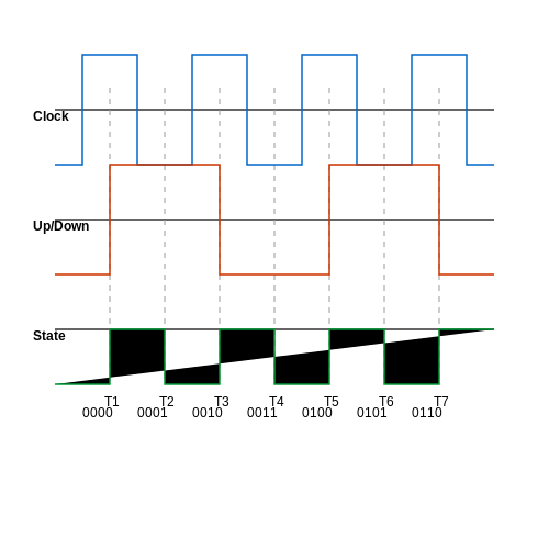
To visualize the operation of the up/down counter, one can draw a timing diagram that represents the clock signal and the corresponding state output. The essential aspect is to indicate how the control signal toggles between up and down counting. When the control input is high, the output will count upwards, whereas, for a low signal, the output will descend.
This functionality is essential in areas where the monitoring of events needs to be bidirectional, such as in production counting systems where products may enter or exit a counting area.
Practical Applications
The applications of up/down counters extend into various fields of electronics and computer engineering:
- Digital Clocks: Maintaining time by counting seconds, minutes, and hours accurately, while allowing for adjustments.
- Frequency Counters: Measuring the frequency of incoming signals through precise counting methods.
- Electronic Voting Machines: Tallying votes, which may increase or decrease depending on selections.
The development of such counters is instrumental in refining user interfaces and enhancing the overall efficiency of electronic devices equipped with counting mechanisms.
For engineers and researchers working on digital systems, understanding and effectively implementing up/down counters can significantly improve system performance and reliability.
2. Counting Sequence
2.1 Counting Sequence
In advanced digital electronics, the counting sequence provides the backbone for various counting mechanisms employed in circuits. Counters can be found in a multitude of applications, from simple timers to complex digital clock systems and signal processors. A thorough understanding of counting sequences is essential for engineers, researchers, and physicists engaged in designing and optimizing electronic systems. To begin our exploration of counting sequences, we first need to define the fundamental nature of a counter. A counter is fundamentally a sequential circuit that generates a sequence of states based on clock pulses. Each clock pulse causes the counter to transition from one state to another, which constitutes the counting operation. The counting sequence can take on various forms, depending on the type of counter used—binary, decimal, or even custom counting sequences. The most common types of binary counters include up counters, which increment the count with each clock pulse, and down counters, which decrement the count. To visualize these operations, consider a simple 3-bit binary counter, which can represent the sequences as follows: - An up counter counts from 000 (0 in decimal) to 111 (7 in decimal): 000, 001, 010, 011, 100, 101, 110, 111. - Conversely, a down counter counts from 111 (7 in decimal) to 000 (0 in decimal): 111, 110, 101, 100, 011, 010, 001, 000. Here, each transition occurs with the triggering of a clock pulse. It is essential to understand that these transitions not only represent the count but also dictate the timing and synchronization of various components within a digital system.Mathematical Representation of Counting Sequences
To formalize our understanding further, let’s consider a binary up counter. The state of the counter at any given time can be represented mathematically. If we denote the current state of the counter as \( Q_n \), the state after one clock pulse can be expressed as: $$ Q_{n+1} = Q_n + 1 $$ In this expression, \( Q_n \) is an integer value representing the current count, and \( Q_{n+1} \) is the resulting value after a clock pulse. The counter will continue this sequence until it reaches its maximum count for a given number of bits, at which point it will reset back to zero (circular counting). For clarity, we can create a more compact mathematical formulation using modular arithmetic. The counter value can be expressed as: $$ Q_n = n \mod N $$ Where \( N \) is the maximum count value, determined by the number of bits in the counter's architecture (for example, \( N = 2^3 \) for a 3-bit counter). This iterative behavior of counting allows for seamless integration into digital circuits, enabling synchronization and data processing in applications ranging from computational algorithms to real-time signal processing systems.Real-World Applications
The practical applications of counting sequences are extensive. Here are a few prominent examples:- Digital Clocks: Counting sequences are employed in the timing mechanisms that keep track of time accurately in numerous consumer electronics.
- Frequency Counters: Used in telecommunications to measure the frequency of incoming signals, allowing for proper signal interpretation and processing.
- Event Counters: In various industrial applications, counting sequences track the number of events or products passing through a certain point, aiding in efficiency and operational metrics.
Conclusion
The counting sequence forms the framework for a myriad of digital systems and applications where precision timing and data tracking are essential. Through this understanding, engineers and researchers can innovate and optimize designs for increasingly complex electronic systems—they can design counters that are not only efficient but also versatile in their applications. The study of counting sequences, hence, remains a critical component of electronics and computer science education, pushing the boundaries of what is possible in digital technology.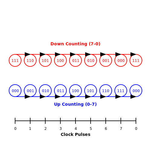
2.2 Counting Speed
Counting speed in digital counters is an essential characteristic that defines their performance and utility. In both scientific research and industrial applications, understanding how quickly a counter can process input signals can influence design choices and applications.Timing and Timing Diagrams
To appreciate counting speed, we must first consider timing specifications. Timing diagrams illustrate the relationship between input signals and the resulting output in digital counters. Usually, these diagrams show voltage levels over time, marking crucial edges, such as rising and falling edges, that trigger the counting process. In most counters, the counting frequency is primarily dictated by the clock signal, which serves as the timing source. The frequency can be defined mathematically as:Propagation Delay
Another key factor affecting counting speed is propagation delay. This is the time taken for an input change to produce an output change. In synchronous counters, every flip-flop processes the input in concert based on the clock signal, whereas in asynchronous (or ripple) counters, the output of one flip-flop serves as the clock signal for the next. The counting speed can be negatively affected by propagation delay in asynchronous counters, leading to a phenomenon known as "race conditions." The total propagation delay (\( t_{pd} \)) for an n-bit asynchronous counter can be approximated by the equation:Real-World Applications
Counting speed has significant practical implications. For instance, in digital signal processing (DSP) systems, counters need to operate at high frequencies to ensure accurate data sampling and processing. Additionally, in data acquisition systems, fast-counting rates are necessary to capture rapid events accurately. The performance of a counter directly impacts the overall speed and responsiveness of the system in both laboratory and industrial settings. Ultimately, understanding counting speed not only aids in selecting the right counter for a specific application but also enhances the design process for a wide range of digital systems that rely on counters for timing, frequency counting, and event tracking. This knowledge empowers engineers to optimize counter speeds, safeguard against propagation delays, and improve the reliability of high-speed digital applications.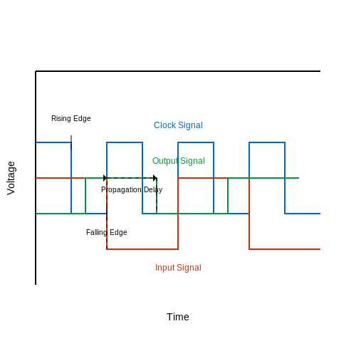
Resetting and Initialization
In the realm of digital electronics, counters serve as fundamental building blocks essential for timing, counting, and sequencing tasks. While their operational functionality is significant, a crucial aspect often overlooked is the mechanism for resetting and initializing these counters. The resulting stability and reliability of counter behavior hinge on these processes, thus warranting a detailed examination.Count Types and Reset Operations
Counters can be broadly classified into two categories based on their counting direction: up counters and down counters. Each category requires specific strategies for resetting and initialization. - Up Counters: These increment their count value on each clock pulse. Upon reset, it’s crucial that the counter not only returns to zero but also does so in a controlled manner, ensuring that associated outputs (like display or indicator systems) reflect this status reliably. - Down Counters: Conversely, down counters decrement their count values. Resetting here also entails returning to a defined maximum value instead of zero, often leading to a rollover effect which can result in count interruptions if not handled properly. For both counter types, effective resetting can be achieved either through synchronous or asynchronous methods. Synchronous resets occur simultaneously with clock pulses, ensuring a coordinated reset operation as a part of the clock cycle. This method favors predictability and stability, especially when employed in larger circuits. In contrast, asynchronous resets allow for immediate resetting regardless of the clock state, offering better responsiveness in key applications, albeit with a potential lag in state synchronization.Initialization Sequence
Initialization prior to operation is another critical aspect. Consider a digital counter in a microcontroller application that starts from a pre-defined count value, rather than simply initializing to zero. To effectively achieve this, a sequence must be established that doesn’t interfere with the counter's operation logic or produce erroneous values. To illustrate, let’s denote an initialization sequence mathematically: Let: - \( C_t \) = Counter value at time \( t \) - \( C_i \) = Initial count value The relationship can be expressed as: $$ C_t = C_i + \Delta C \cdot T $$ where: - \( \Delta C \) = Change in count per clock cycle - \( T \) = Number of clock cycles elapsed This formula ensures that the counter maintains a continuous operation transitioning from the initialized state through its counting sequence, without unintended resets or jumps.Practical Applications and Design Considerations
In real-world applications, effective resetting and initialization of counters are indispensable. Consider a digital clock system where precise time tracking is critical. Here, counters not only need to reset accurately upon power-on but also require initialization to the current time rather than the default zero state. In industrial automation, counters regulate machinery operations, controlling cycle counts for processes such as pick-and-place operations. Ensuring that these counters are reset and initialized correctly prevents operational faults and enhances reliability in production environments. To ensure the success of these counters, designers must conduct extensive testing under varying conditions, accounting for not only the electrical characteristics of the components but also the thermal and noise environments they may encounter. This exhaustive approach safeguards against malfunctions caused by improper reset scenarios or unanticipated initialization states. In conclusion, resetting and initialization are pivotal in counter design, influencing their reliability in a myriad of applications. Understanding the underlying principles and their implementation not only facilitates the desired functionality but also enhances the overall robustness of electronic systems.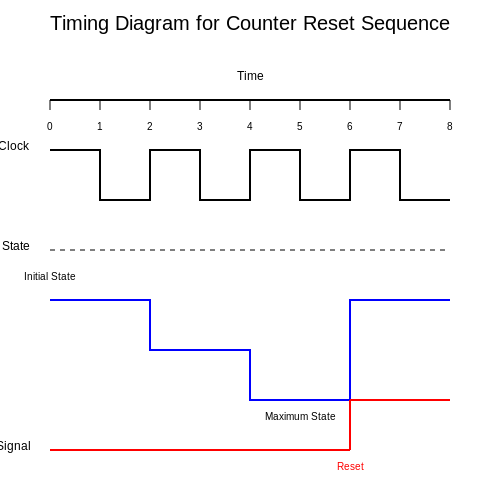
2.4 Load Operation
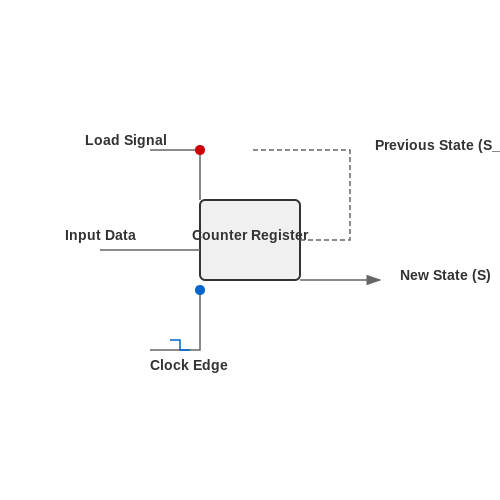
The operation of counters, particularly in digital electronics, often requires an understanding of the load operation. This process is essential for how counters manage their state when receiving inputs, especially in more complex applications such as data acquisition and digital signal processing. The load operation is a critical action wherein a counter can store a specific value when enabled, rather than incrementing or decrementing with each clock pulse. Understanding this functionality is crucial for advanced counting mechanisms, especially in synchronous and asynchronous designs.
Understanding the Load Input
The load input on a counter allows for the parallel loading of data into its register, enabling the counter to directly set its output to a predetermined value. This is particularly useful in applications where precise control of counting sequences is required, such as in timers or frequency dividers.
When the load signal is activated, the data present on the counter's input lines is transferred to its internal register, overwriting any existing count. This process typically occurs on a specific clock edge and may depend on the counter's design—be it synchronous or asynchronous. Synchronous counters change their state with respect to a common clock signal, while asynchronous counters may change their states based on different triggering signals, leading to potential timing issues.
Mathematical Representation
The load operation can be mathematically represented as follows. Consider a binary counter with a load value represented by the vector A (where A is a bit vector consisting of n bits). When the load operation is triggered, the new state of the counter S can be expressed as:
In the above equation, S is the new state, S_{prev} is the current count, and the operation depends on whether the load signal is active.
Practical Applications
Load operations are extensively used in a wide range of applications, such as frequency counters, digital clocks, and programmable logic devices. For example, in a digital clock, the ability to load a specific time is essential for setting the correct time without altering the running count. In frequency counters, the counter can load a specified reference frequency against which other signals can be measured or compared.
Additionally, engineers often utilize the load feature during calibration procedures or when interfacing with external data sources. For instance, in a digital voltmeter, the ability to load measured values into a display register enhances user interactions and measurement accuracy.
It is important to understand that while the load function provides significant control, it also introduces design complexity that requires careful consideration during the design phase. For instance, managing race conditions and ensuring proper clock domain crossing in systems employing both loaded and incremented counts can be challenging.
In summary, the load operation is a fundamental aspect of counter functionality, allowing for precise state management in advanced digital systems. Mastery of load operations enhances the capability to design robust, efficient counting mechanisms suitable for various applications.
3. Digital Clocks
3.1 Digital Clocks
Digital clocks represent one of the most ubiquitous applications of counters in practical electronics. Unlike their analog counterparts, which rely on mechanical movements to indicate time, digital clocks use electronic counting circuits to keep track of time with precision. In this section, we will delve into the inner workings of digital clocks, emphasizing their architecture, operational principles, and the role of counters in their functionality.
Architecture and Components
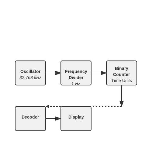
At the core of a digital clock is a system of counters that increment based on a precise timekeeping source, typically a quartz crystal oscillator. The basic architecture of a digital clock includes:
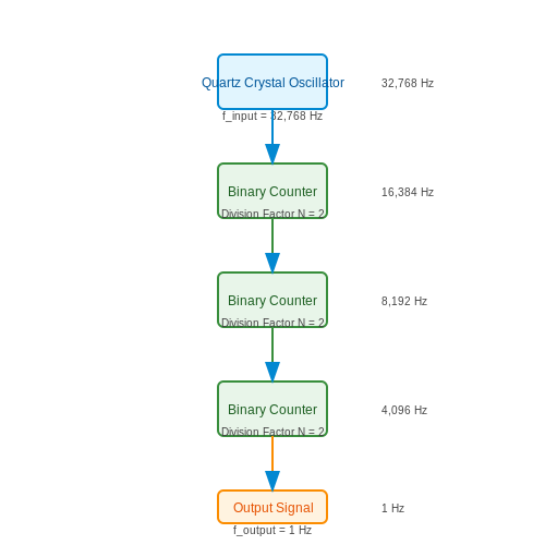
- Oscillator: A quartz crystal that oscillates at a specific frequency, often 32.768 kHz, to provide a stable time base.
- Frequency Divider: A series of flip-flops configured to divide the oscillator's frequency down to a 1 Hz signal, which corresponds to one second.
- Counter: A binary or decade counter that keeps track of seconds, minutes, and hours.
- Decoder: Converts the binary output of the counter into a format suitable for display, typically in decimal form.
- Display: An electronic display (LCD, LED, etc.) that visually represents the current time.
Operational Principles
The operation of a digital clock can be conceptually segmented into two primary phases: counting and displaying. The oscillator continuously produces oscillations, and the frequency divider works to reduce these oscillations to a manageable level. For clarity, let's derive how a binary counter can be used to measure time.
Frequency Division and Counting
Starting from the 32.768 kHz signal generated by the crystal, we need to divide this frequency to yield a signal that increments every second:
Here, \( f_{out} \) is the output frequency (1 Hz), \( f_{in} \) is the input frequency (32.768 kHz), and \( N \) is the division factor:
This division factor requires a counter that can operate with a base-2 system, hence the need for a 15-stage binary counter (since \( 2^{15} = 32,768 \)). The output of this counter will toggle every time it counts up to 32,768, effectively creating a one-second pulse.
Incrementing Time Units
As the counter increments, the structure of the digital clock typically allows for the segmentation of time into hours, minutes, and seconds. Each of these components can be managed through a series of sub-counters. For instance:
- The seconds counter resets upon reaching 60.
- The minutes counter increments by one with each reset of the seconds counter.
- The hours counter increments with the reset of the minutes counter, typically rolling over at 24 for a 24-hour clock.
Relevance and Applications
Modern digital clocks are not limited to simply displaying time; they find applications in various fields such as:
- Timing Devices: Used in laboratories for precise timing of experiments.
- Navigation Systems: Integral in GPS technology where accurate timing and synchronization are critical.
- Consumer Electronics: Found in everything from microwaves to entertainment systems where time management is essential.
As technology advances, the integration of digital clocks into more complex systems such as IoT devices signifies their continued evolution and relevance in providing accurate timekeeping.
Looking Ahead
While we have covered the fundamental workings of digital clocks, the next section will explore more complex counting mechanisms and their applications in various timekeeping and signaling systems. Understanding these principles is foundational for anyone looking to innovate in the realm of electronic timing devices.
3.2 Frequency Division
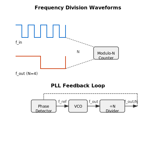
The concept of frequency division is integral to various applications in electronics, particularly in the realm of clock signals and synchronous digital circuits. At its core, frequency division involves reducing the frequency of a periodic signal, thereby yielding a new signal whose frequency is a fraction of the original. This process is essential in various applications, such as signal processing, digital communication systems, and in the design of counters.
Frequency dividers or frequency dividers circuits, often realized with flip-flops, play a pivotal role in this particular domain. As each flip-flop effectively divides the input frequency by two, a series of cascaded flip-flops can achieve larger division ratios. For example, if a clock signal of frequency \( f_{in} \) is applied to a chain of \( n \) flip-flops, the output frequency \( f_{out} \) can be expressed as:
This equation makes it evident that the number of flip-flops dictates the extent of frequency division. A practical instance of this can be found in digital clocks, where a high-frequency oscillator is used to generate a time base of one second by utilizing a combination of flip-flops.
Practical Implementation
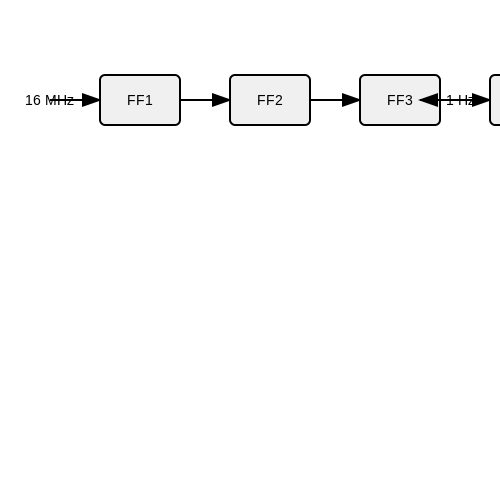
To illustrate a common application, consider the task of creating a 1 Hz signal from a 16 MHz clock source. By utilizing a series of four flip-flops (since \( 2^4 = 16 \)), the output will yield a frequency of:
This principle underlies many applications from simple timers to complex frequency synthesizers. It also serves as a foundational aspect for phase-locked loops (PLLs) and other signal conditioning applications.
Types of Frequency Dividers
There are generally two types of frequency dividers: asynchronous (or ripple) dividers and synchronous dividers.
- Asynchronous Dividers: These utilize flip-flops in a cascading configuration where the output of one flip-flop triggers the next. The propagation delay can introduce timing issues, especially at high frequencies.
- Synchronous Dividers: All flip-flops are clocked simultaneously, significantly reducing errors due to propagation delay, making them preferable in applications requiring precise frequency division.
Another noteworthy application of frequency division beyond simple timing tasks is in frequency modulation systems. Frequency dividers in these systems help convert high-frequency signals into lower frequency representations, enabling efficient signal processing and transmission.
In summary, understanding frequency division extends beyond merely halving frequencies; it opens up a broad landscape of electronic applications. From timing circuits in microcontrollers to advanced communications systems, frequency division is a fundamental concept that enhances the efficacy and utility of electronic devices.
3.3 Event Counting
Event counting is a critical process in various fields, including electronics, physics, and data acquisition systems. It is the systematic measurement of discrete events, often transforming physical phenomena into quantifiable data. Understanding and implementing event counting systems allow engineers and researchers to analyze and interpret phenomena across different applications such as timekeeping, digital logic, signal processing, and experimental mechanics.Counter Basics
Before delving deeper into event counting, it is essential to revisit the core operation of digital counters. A counter is essentially a sequential digital logic circuit that counts pulses. It can be implemented using flip-flops, where the output of the flip-flop represents the count of input pulses. The most simplistic form of a counter is a binary counter, which maintains its state in binary form and increases or decreases with each pulse based on its configuration (up/down). The primary operation of a counter may be expressed mathematically, showcasing the relationship between input pulses (N) and corresponding output states (S):Types of Event Counters
Event counting can be broadly categorized into two types: synchronous and asynchronous counting. Synchronous counters are those where all flip-flops are triggered simultaneously by a common clock signal. This design mitigates the propagation delay issues, leading to faster operation and more reliable counting at higher frequencies. An example would be a binary ripple counter, where each flip-flop toggles based on the output of the previous flip-flop. Asynchronous counters, on the other hand, have flip-flops that do not receive their clock signal simultaneously. Instead, the clock signal propagates through each flip-flop consecutively. While this can simplify design, it often introduces complications related to timing and delays, leading to what is known as "ripple" counting, where the final count may experience a time lag.Practical Applications of Event Counting
Event counting systems occupy valuable real estate in numerous real-world applications:- Time Measurement: Clocks and timers utilize counters to keep accurate time, relying on pulses derived from oscillators to advance minute or second counts.
- Digital Electronics: In digital devices, counters serve as foundational components such as frequency dividers, digital voltmeters, and microcontrollers.
- Data Acquisition: Experimental setups, particularly in physics experiments, often require event counters to collect data on particle interactions, providing vital insights into reactions occurring at quantum levels.
- Manufacturing Processes: In industrial automation, counters can track product counts on a production line, alerting systems when predetermined quantities are reached.
Designing an Event Counting System
When designing an event counting system, several critical factors need consideration: 1. Event Source: Determining the nature of the event being counted (e.g., mechanical switch, optical sensor) dictates the type of sensor and counter configuration. 2. Counter Type: Choose between up or down counters based on whether the count should increment or decrement. 3. Output Handling: Consider how to store, display, or transmit the count output. Interface circuitry or digital displays may be necessary depending on the application. 4. Timing and Clocking: Ensure that the clock signal integrity is maintained and choose appropriate clock speeds to guarantee that events are not missed. To summarize, understanding event counting and its underlying principles is fundamental for advanced engineers and researchers alike. Mastering these concepts can equip professionals with the necessary insights to devise sophisticated systems capable of counting and analyzing events with precision and efficiency.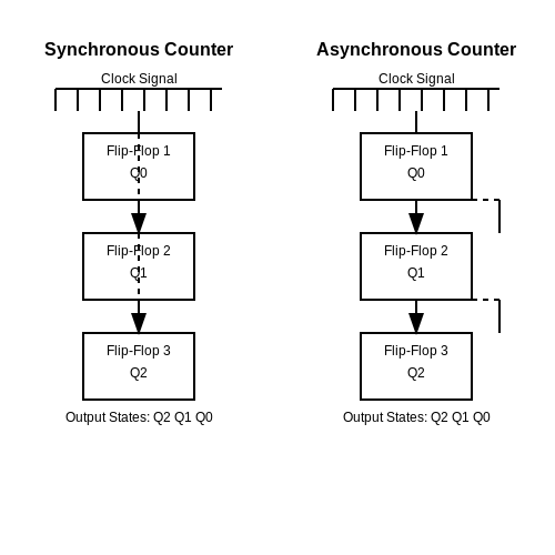
3.4 State Machines
The role of state machines in digital systems is a profound concept that extends from theoretical frameworks to practical implementations. State machines can be seen as mathematical models of computation, representing a system's behavior through states and transitions. In the context of counters, state machines serve not only as effective counting mechanisms but also as foundational components for more complex systems.
Understanding State Machines
A state machine consists of a finite number of states, including an initial state, and transitions between these states based on input signals. This can be expressed in two primary forms: Mealy and Moore machines. In a Mealy machine, the output depends on the current state and the input, while in a Moore machine, the output is solely based on the current state. This distinction significantly influences their design and application in counters.
Mealy vs. Moore Machines
- Mealy Machines: The output can change immediately in response to input changes, resulting in potentially fewer states compared to Moore machines.
- Moore Machines: Outputs change only at state transitions, which simplifies the timing analysis but may require more states to implement complex behavior.
Mathematical Representation
The behavior of state machines can be encoded mathematically using finite state automata (FSA). This involves defining a tuple containing the set of states S, the set of input symbols I, the set of output symbols O, the transition function δ, the output function λ, and the initial state s0.
The formal definition is as follows:
In this formulation:
- S: Finite set of states.
- I: Finite set of input symbols.
- O: Finite set of output symbols.
- δ: State transition function, where δ: S × I → S.
- λ: Output function, where λ: S → O.
- s0: Initial state from which any computation starts.
Practical Applications
In practical applications, state machines are crucial for designing sequential circuits, including counters, registers, and control units in microprocessors. For instance, a binary counter can be modeled as a sequential state machine comprising states corresponding to binary values. Each clock pulse initiates a transition to the next state, effectively counting in binary.
Moreover, state machines are used extensively in software for protocol modeling, game development, and managing user interfaces, where distinct operational states must be tracked and managed efficiently.
Case Study: Binary Counter as a State Machine
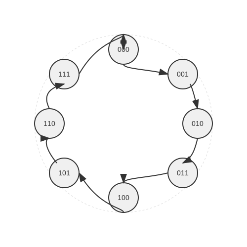
Consider a simple 3-bit binary counter. This counter has eight states, from binary 000 to 111. It operates on a sequence of clock pulses, and upon each pulse, it transitions to the next state until it reaches its maximum count, after which it returns to zero. The state transition diagram can easily depict how the counter progresses through its states.
Below is an illustration of the state transitions for the binary counter:
When considering the frequency of operation, the clock speed and the state machine's complexity significantly affect performance in sequence generation. As digital circuits advance, the need for efficient state machine designs becomes paramount, particularly in high-frequency environments.
Conclusion
State machines serve as the backbone for understanding and designing counters and other sequential circuits. Their applications not only extend into digital electronics but also influence areas like computer science and software engineering, highlighting their versatile nature.
4. Logic Diagrams for Counters
4.1 Logic Diagrams for Counters
In the realm of digital electronics, counters serve as clock-driven devices that tally events, pulse widths, or frequencies in binary form. These versatile tools have prominent applications, ranging from digital clocks to frequency counters. Understanding the logic diagrams associated with various types of counters is essential for effectively designing and troubleshooting digital systems.Types of Counters
Counters generally fall into two categories: synchronous and asynchronous. Synchronous counters have all flip-flops driven by a common clock signal, ensuring that the state transitions occur simultaneously. In contrast, asynchronous counters, often referred to as ripple counters, exhibit a staggered state change due to individual flip-flops being triggered by the output of their preceding counterparts.Logic Diagrams and Flip-Flops
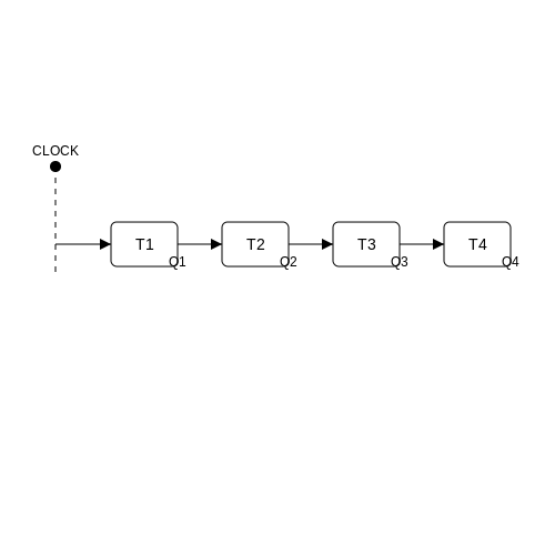
The fundamental building block of counters is the flip-flop, which can store a single bit of information. The two most common types are the D flip-flop and the T flip-flop. D Flip-Flop: This flip-flop is triggered on the edge of the clock signal. It captures the value present at its D (data) input whenever the clock rises (or falls, depending on design specifics). The logic diagram for a D flip-flop features two primary inputs: the D input, which is the data line, and the clock line. T Flip-Flop: This flip-flop toggles its output state whenever the clock signal transitions. The T input determines whether the flip-flop changes state (when T is high) or maintains its current state (when T is low). Now, let’s analyze the logic diagrams for a simple 4-bit binary counter using T flip-flops as our building blocks: 1. State Transition Logic: A 4-bit counter counts from 0 (0000) to 15 (1111). Each flip-flop represents a single binary digit (bit), with the least significant bit (LSB) controlled by the first T flip-flop. The subsequent flip-flops toggle based on the previous flip-flop’s output. 2. Generating the Logic Diagram: In this setup, we connect the clock signal to each T flip-flop. The first flip-flop toggles with each clock pulse. The second flip-flop toggles on every second pulse (when the first flip-flop’s output transitions from 0 to 1), and thus the clock signal of this flip-flop will be taken from the output of the first flip-flop. This cascaded connection establishes the ripple effect. To visualize the logic diagram, imagine a series of T flip-flops: - T1 connected to the CLOCK signal. - T2 connected to the output of T1. - T3 connected to the output of T2. - T4 connected to the output of T3. This arrangement efficiently captures the cascading toggling signals. Below is a basic representation of a 4-bit binary up counter based on T flip-flops:Practical Applications of Counters
The applications of counters extend widely within multiple fields of electronics:- Frequency Measurement: Used in frequency counters to measure the number of occurrences of a signal in a given time period.
- Digital Clocks: Fundamental in digital timekeeping devices, where each second represents an increment of a specific counter.
- Event Counting: Essential in various industrial applications where the tallying of production pieces is necessary.
4.2 Using Flip-Flops in Counters
In the realm of digital electronics, flip-flops play a pivotal role as fundamental building blocks of memory and state retention. Their application extends into various types of counters, which are integral components in many electronic systems, from simple timers to complex sequential circuits. In this section, we will delve into how flip-flops are utilized in counters, specifically focusing on their configurations, operational principles, and practical applications.Understanding Flip-Flops
Before exploring their application in counters, let's briefly define flip-flops. A flip-flop is a bistable multivibrator, meaning it can exist in one of two stable states. The two primary types of flip-flops used in counters are D flip-flops and T flip-flops. The D flip-flop captures the value of the input data line (D) at every clock edge and retains it until the next clock cycle. The T flip-flop, on the other hand, toggles its state when its T input is high on the triggering clock edge. The predominant operations of these flip-flops serve as the foundation for counting mechanisms. Their configuration determines the counting behavior, such as asynchronous or synchronous counting, which is critical for many digital applications.Counter Types and Their Operation
Counters can be broadly classified into two categories: asynchronous and synchronous counters.- Asynchronous Counters (Ripple Counters): In an asynchronous counter, the flip-flops are not driven by a common clock signal; rather, the output of one flip-flop serves as the clock input for the next. This results in a "ripple" effect, where the change in state propagates through the flip-flops, creating a delay that can affect counting speed and reliability.
- Synchronous Counters: In contrast, synchronous counters utilize a common clock signal that triggers all flip-flops simultaneously. This design minimizes propagation delay and enhances stability, making them preferable for high-speed applications.
Asynchronous Counter Design
The simplest form of an asynchronous binary counter consists of a series of T flip-flops. To design a 2-bit asynchronous counter, we require two T flip-flops, where the first flip-flop toggles for every clock pulse, and the second toggles for every time the first flip-flop transitions from high to low.The output states for a 2-bit asynchronous counter can be represented as:
- State 00
- State 01
- State 10
- State 11
Synchronous Counter Design
Constructing a synchronous counter involves connecting the T inputs of the flip-flops in a way that enables them to respond predictably to the clock signal. A 3-bit synchronous counter, for example, uses three T flip-flops connected to a common clock and utilizes combinational logic to control the T inputs and define the counting behavior.The operation table would be as follows:
| Clock Pulse | Q2 | Q1 | Q0 |
|---|---|---|---|
| 1 | 0 | 0 | 0 |
| 2 | 0 | 0 | 1 |
| 3 | 0 | 1 | 0 |
| 4 | 0 | 1 | 1 |
| 5 | 1 | 0 | 0 |
Conclusion and Practical Applications
The integration of flip-flops in counter design illustrates the intersection of theoretical principles and practical engineering. These counters find extensive applications in digital clocks, frequency dividers, event counters, and more, highlighting their versatility within electronic systems. As digital requirements advance, understanding and leveraging the unique characteristics of flip-flops in counters will remain a cornerstone of circuit design and implementation. With a solid grasp of these concepts, engineers and researchers are well-equipped to employ flip-flops in novel applications, leveraging their potential to develop more efficient and reliable digital systems.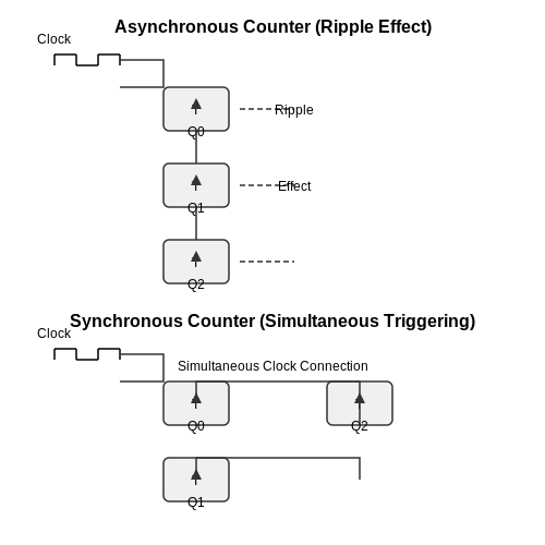
4.3 Achieving Higher Counting Ranges
In count-based applications ranging from digital frequency meters to event counters in high-energy physics experiments, increasing the counting range while maintaining accuracy is a significant challenge. Traditional binary counters, while straightforward, are limited in their maximum count capacity by the width of their registers. This section explores advanced techniques for achieving higher counting ranges, focusing on scalable architectures and specialized counter designs.
Understanding Limitations of Conventional Counters
Conventional binary counters are typically implemented using flip-flops, where each flip-flop represents a single binary digit (bit). The maximum count of an n-bit binary counter is given by:
This means that a 4-bit counter can count up to 15, while an 8-bit counter can only reach 255. As applications demand larger counting ranges, relying solely on binary counters becomes inefficient. Here, we can explore several advanced techniques that help in overcoming these limitations.
Using Multi-Stage Counting Techniques
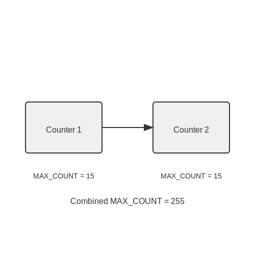
One effective approach to achieve higher counting is to utilize multi-stage design architectures. This involves cascading smaller counters to create a larger virtual counter. For instance, a two-stage configuration consisting of two 4-bit counters can count up to:
By cascading them, the count range expands significantly without requiring a complete redesign of the counter logic. In most cases, the cascading method retains high speed and accuracy, as long as proper synchronization and resetting procedures are followed.
Employing Decade Counters and Counting Modulus
An extension of traditional counting can be achieved by employing decade counters, which count to ten before resetting rather than two. A decade counter can be combined, where several such counters work together to provide more extensive counting capabilities.
For instance, two decade counters could theoretically count up to:
This method offers an elegant solution for applications like digital clocks or event logging systems, where counts are often suited to decimal representation.
Utilizing Memory Techniques for High-Resolution Counting
Additionally, integrating memory components, such as RAM or FIFO (First-In-First-Out) buffers, in conjunction with counters allows for significantly larger and more flexible counting ranges. This approach is particularly useful when tracking events over long periods without immediate processing needs.
Memory-augmented counting allows for asynchronous counts and can help manage overflows gracefully. This is essential in high-energy physics experiments where precise event counters are required to gather data from particle detectors, without losing vital information due to overflow errors.
Real-World Applications
The applications of higher counting ranges are abundant across various fields:
- Telecommunications: Base stations utilize multi-stage counters for signal processing and event logging, ensuring that high-speed data transfers are counted accurately.
- Automotive Engineering: In modern vehicles, event counters monitor miles, fuel usage, and component wear, often using decade counters for ease of readout.
- High-Energy Physics: Counting particles in accelerators requires sophisticated counting systems capable of handling data from numerous simultaneous events.
Through the combination of cascading counters, leveraging decade counters, and utilizing memory solutions, engineers and researchers can create efficient counting systems capable of meeting the demands of contemporary technological challenges.
5. Common Issues
5.1 Common Issues
Counters are vital components in digital electronics, often used in applications ranging from basic counting tasks to complex frequency division and timekeeping. However, as versatile as they are, counters can be prone to various issues that can hinder performance and accuracy. Understanding these common issues is essential for ensuring their reliable operation in practical applications.
Glitches and Race Conditions
One of the most prevalent problems encountered with counters, particularly those based on flip-flops, is the potential for glitches and race conditions. A glitch occurs when a signal momentarily changes due to differences in signal propagation times across various paths. These glitches can lead to erroneous counts if not properly managed.
The risk of glitches is especially pronounced in asynchronous counters, where changes are made without a global clock signal to synchronize the transitions. To mitigate glitches in synchronous designs, engineers often employ techniques such as debouncing circuits and careful arrangement of flip-flops to minimize propagation delays.
Practical Example
A significant real-world application of debouncing can be found in digital clocks. The transition of singular pulses from buttons (to set time parameters) can produce rapid, undesirable oscillations that lead to multiple counts for a single press. Implementing a debouncing circuit ensures the button press is counted correctly.
Overflow and Underflow
The inherent limitation of counter types often leads to overflow or underflow issues. For instance, binary counters, depending on their design, may wrap back to zero after reaching a predetermined maximum count (e.g., a 4-bit counter resets after 15). Understanding the maximum count is critical, especially in applications such as event counting, where missing counts can lead to miscalculation.
Here, \( n \) is the number of bits, and \( N_{\text{max}} \) is the maximum count before overflow.
Application Insight
In real-time systems, overflow handling is critical. For instance, in telemetry systems, bypassing overflow could result in the loss of valuable data. Implementing a mechanism that can either reset the counter or trigger an interrupt to handle this scenario is vital for maintaining system reliability.
Timing Issues
Timing issues can severely impact counter performance, particularly in high-speed applications. Timing violations where setup and hold times are exceeded can lead to incorrect data being latched by flip-flops. This is particularly relevant in circuits with multiple levels of logic or in setups where signal delays are significant.
To mitigate these issues, engineers often specify clock periods that exceed the cumulative propagation delay across the counter. Additionally, the use of skew-tolerance techniques can further reduce timing-related errors.
Example of Timing Analysis
Consider a counter designed for a high-speed operation, where the clock frequency is 50 MHz. To analyze impact on performance, engineers would calculate the required setup time \( T_{setup} \) based on the specifications of the flip-flops used and adjust for the total propagation delays in the signal paths.
Here, \( T_{pd1} \) and \( T_{pd2} \) are the propagation delays of the flip-flops in the design.
Power Consumption and Heat Dissipation
With complex digital designs, power consumption and heat generation can become significant concerns, particularly in battery-operated or densely packed circuit boards. As counters and other components operate, they draw power, and excessive heat can lead to reliability issues or even catastrophic component failure.
Utilizing low-power design techniques, such as adjustable clock frequencies and adaptive voltage scaling, can immensely help in reducing power draw and managing heat generation.
Real-World Example
In applications such as wearable technology, where a counter might be used for tracking movements or counting steps, managing power consumption is essential to ensuring prolonged operation without frequent recharging.
In summary, while counters serve as foundational elements in countless electronic devices, several issues such as glitches, timing violations, overflow, and power consumption must be carefully considered and optimized in order to ensure reliable and accurate performance in all scenarios.
5.2 Diagnostic Techniques
Counters are fundamental components in both digital electronics and signal processing; their effectiveness often hinges on proper diagnostic techniques. Understanding these techniques can significantly enhance the reliability and performance of counter circuits, especially in complex applications such as communication systems and automated processes.
Understanding the Importance of Diagnostics
Diagnostic techniques serve as essential procedures aimed at identifying and resolving issues within counter circuits. These issues can lead to failures in timing, counting accuracy, and ultimately, functionality. By employing advanced diagnostic tools and methodologies, engineers can ensure robust performance in their designs.
Common Diagnostic Techniques
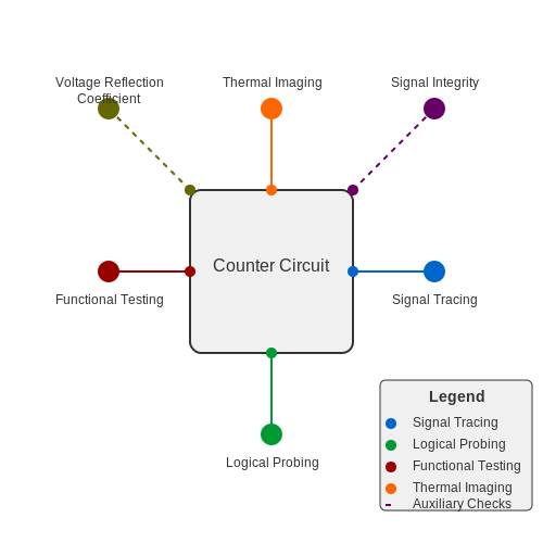
- Signal Tracing: This technique involves monitoring the signal at various points within the counter circuit to locate where faults occur. It gives insight into the behavior of different stages, allowing one to identify erroneous outputs.
- Logical Probing: Using logic analyzers, engineers can probe the states of various flip-flops and gates within counters to verify their operation against expected behaviors. This is particularly useful in detecting race conditions and setup/hold time violations.
- Functional Testing: By verifying the logical functionality of the counter through simulation tools or hardware testing, one can ensure the counter performs as expected across its operational range.
- Thermal Imaging: An often-overlooked method, thermal imaging can detect hotspots caused by excessive current, which may hint at failing components within a counter's circuitry.
Signal Integrity Analysis
Another critical facet of diagnostics in counters is maintaining signal integrity. Signal integrity issues, such as reflections or crosstalk, can severely disrupt the operation of counter circuits. Engineers often utilize simulation software to model signal propagation and analyze how it affects counting processes.
Mathematical Modeling of Signal Integrity
The integrity of signals in a counter can be mathematically modeled using transmission line theory. A simplified expression for the voltage reflection coefficient (Γ) can be derived to understand signal loss due to impedance mismatch:
Where:
- Γ is the voltage reflection coefficient,
- Z_L is the load impedance, and
- Z_0 is the characteristic impedance of the transmission line.
By analyzing Γ, an engineer can deduce the impact of various load conditions on signal transmission within a counter and devise appropriate adjustments to mitigate loss.
Practical Applications of Diagnostic Techniques
Diagnostic techniques find extensive applications in various fields. For instance, in aerospace systems, counters are pivotal in flight data recorders, where reliability is crucial. Implementing sophisticated diagnostic methods ensures that any failure in counting systems is promptly identified, enhancing operational safety. Similarly, in consumer electronics, counters enable functionalities like digital clocks and timers, where precision in counting is paramount.
In conclusion, mastering diagnostic techniques for counters not only aids in troubleshooting but also serves to optimize performance and extend the lifespan of electronic devices. Such competencies are invaluable in fields demanding high reliability and precision.
5.3 Testing and Validation
Testing and validation of counters is a crucial step in ensuring their reliability and accuracy in applications ranging from digital clocks to complex embedded systems. As counters play a foundational role in digital electronics, the need for stringent testing protocols can’t be overstated. This section explores the methodologies employed to test and validate counters, focusing on both their functional and performance aspects.Functional Testing of Counters
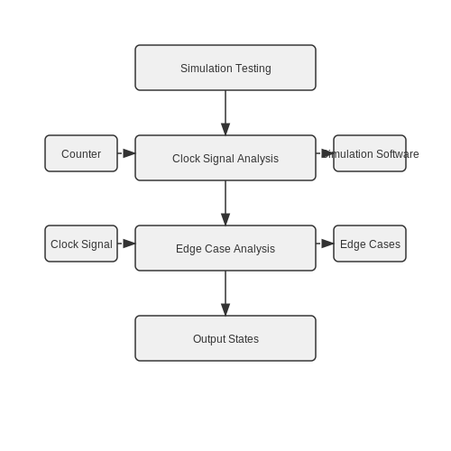
Functional testing primarily assesses whether the counter behaves as expected under a variety of conditions. This includes verifying the count sequence, maximum and minimum value detection, carry operations, and reset functionalities. Engineers typically utilize a combination of simulation tools and physical testing setups for thorough validation. Functional Test Procedures: 1. Simulation Testing: Before deploying hardware, counters can be modeled using simulation software (e.g., ModelSim, LTSpice). This allows for testing various count sequences and states without the risks associated with physical prototypes. 2. Clock Signal Analysis: The input clock frequency affects counting speed and accuracy. By applying known clock signals and observing output, one can ensure the counter increments correctly. 3. Edge Case Analysis: Testing boundary conditions (e.g., counting from zero to maximum, overflow conditions) helps verify that the counter behaves predictably during extreme scenarios.Performance Validation
Once functional correctness is confirmed, performance validation is necessary to analyze the operational attributes such as speed, power consumption, and temperature stability. Key metrics include: - Propagation Delay: Measure the time it takes for the counter to reflect a change in state after a clock pulse. This can be crucial in high-speed applications where timing is critical. - Power Consumption: Assess dynamic and static power consumption of the counter circuits under varying operational frequencies. - Thermal Performance: Prolonged operation can lead to heating, which can affect the counter's performance. Hence, a thermal test evaluates the counter under extended operational periods to ensure reliability.Practical Applications of Testing and Validation
Testing counters is essential not just in academic or theoretical realms but also in practical applications that significantly impact daily life: - Digital Clocks: Using counters to track elapsed time requires high reliability and accuracy. Testing ensures users can trust the displayed time accurately reflects reality. - Frequency Counters: These devices measure frequency in communication systems. Extensive testing guarantees that the input frequency is accurately translated into digital signals. In conclusion, both functional and performance testing of counters forms the backbone of their reliability and effectiveness in diverse applications. Ensuring that counters operate as designed leads to improved system performance and fosters advances in technology.In the next subsection, we will delve deeper into advanced testing techniques, including statistical methods and automation in testing protocols.
6. Books on Digital Electronics
6.1 Books on Digital Electronics
- Digital Design By M. Morris Mano and Michael D. Ciletti — This book offers a comprehensive overview of digital design principles, including detailed sections on counters and sequential circuits, vital for achieving a deeper understanding of advanced digital electronics.
- Fundamentals of Digital Circuits by A. Anand Kumar — A detailed exploration of digital circuit techniques, focusing on the design and applications of counters. The narrative combines theoretical aspects with practical applications, vital for engineers and students.
- Digital Principles and Applications by Donald P. Tocci — An essential resource that covers digital logic with practical insights regarding counters and their functionality within larger digital systems, indispensable for advanced learners.
- Digital Design with RTL Design, VHDL, and Verilog by Frank Vahid — Provides a modern take on digital design using hardware description languages, offering in-depth explanations of counters within digital systems design and implementation.
- Digital Design by John F. Wakerly — Addresses both theoretical and practical facets of digital electronics, with dedicated chapters on counters and sequential logic circuits, crucial for researchers and practitioners alike.
- Contemporary Logic Design by Gaetano Borriello and Randy H. Katz — This textbook covers modern digital techniques including detailed segments on counter designs, providing a critical perspective for academicians and designers in the field.
- Principles of Digital Electronics by G. Jackson — Offers a comprehensive view on digital electronics principles with practical examples of counter applications in various systems, important for both theoretical and practical insights.
6.2 Research Articles on Counter Design
In the landscape of digital electronics, counters are fundamental components widely used in various applications, ranging from simple timing devices to complex communication systems. Researchers continually explore enhancements in counter design to improve efficiency, speed, and functionality. This subsection explores recent research articles and their contributions to the field of counter design, offering insights into cutting-edge advancements and methodologies.Cutting-Edge Counter Design Techniques
The design of digital counters has evolved significantly due to advances in technology and changing application requirements. Improving speed, reducing power consumption, and optimizing structural complexity are ongoing challenges. Advanced techniques often explore novel configurations and utilize high-performance materials and architectures.- High-Speed Counter Design in CMOS Technologies — This paper discusses CMOS-based high-speed counter designs that focus on minimizing latency in advanced digital circuits, essential for real-time data processing applications.
- Low-Power Counter Architectures for Embedded Systems — The study explores counter architectures optimized for reduced power consumption in embedded systems, highlighting innovations in materials and circuit topology.
- Novel Counter Design for Quantum Computing — An insightful examination of counter designs tailored for quantum computing environments, revealing potential improvements in quantum-level signal processing.
- Fault-Tolerant Counter Design in Space Applications — The article presents counter designs aimed at enhancing fault tolerance in space-based applications, crucial for maintaining performance in hostile environments.
- Digital Design: A Systems Approach — While not exclusively focused on counters, this book covers system-level digital design, offering readers comprehensive insights into integrating counters within larger systems.
- Variable Frequency Counter Design for Adaptive Systems — This paper examines counter systems that support variable frequency operations, emphasizing adaptability for dynamic environments.
- Reconfigurable Counters for Energy-Efficient Designs — The research highlights techniques for designing reconfigurable counters that optimize energy efficiency while maintaining performance across diverse applications.
Practical Applications and Future Trends
Advancements in counter design directly influence numerous fields, including telecommunications, computing, and automation. As technology progresses, the importance of developing counters that offer higher levels of integration, performance, and customization grows. Future trends anticipate further integration with AI-driven systems for enhanced autonomous decision-making capabilities and predictive analytics. In conclusion, staying abreast of the latest research in counter design enables engineers and researchers to leverage these innovations effectively within a wide array of technologies. Continued exploration and collaborative efforts in this domain promise significant enhancements to digital and quantum systems alike.6.3 Online Resources and Tutorials
- Electronics Tutorials - Counters — This resource offers a comprehensive guide on counter circuits, including different types and their applications. It's a valuable starting point for understanding the fundamental principles of counters.
- All About Circuits - Counter Circuits — A detailed exploration into the design and function of digital counters, providing circuit diagrams, applications, and in-depth theory explanations suitable for advanced learners.
- Components 101 - Types of Digital Counters — Discusses the various types of digital counters, their specific uses, and how they function in electronic applications, enabling engineers to select the right counter for their projects.
- SparkFun - Counter Project Tutorial — Offers a hands-on project that explains how to create a basic counter using simple electronic components, enhancing practical understanding through demonstration.
- Circuits Today - Counter Tutorial — This tutorial provides a step-by-step guide to understanding counters, with examples and diagrams to illustrate key concepts, especially beneficial for those who prefer visual learning.
- TutorialsPoint - Digital Electronics Counters — An educational platform that delivers a concise yet informative overview of counters, covering asynchronous and synchronous designs and their comparative advantages.
- YouTube - Digital Counter Design — A video tutorial that delves into the design and operation of digital counters, leveraging animation and on-screen demonstrations to clarify complex topics visually.
- Circuit Digest - Digital Electronics Basics — Although this tutorial covers the broader topic of digital electronics, it includes in-depth sections on counters, detailing their types and real-world applications in complex systems.